
1. |  | |||||
2. |
| |||||
3. | Start Creo Elements/Direct Annotation: click > . The Modules dialog box opens. On the Applications pane, in the Included section, click Annotation. | |||||
4. | Create a Drawing. Click the Annotation tab on the ribbon and then, in the Setup group, click  New Drawing. The Create Drawing dialog box opens. New Drawing. The Create Drawing dialog box opens. | |||||
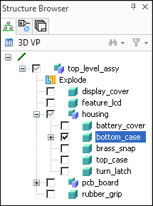
5. | Select an Owner for the drawing: click Owner in the Create Drawing dialog box, clear top_level_assy and double-click bottom_case in the Structure Browser, as shown in the image below.
 | |||||
|
6. | Define Up Dir, as shown in the image below. 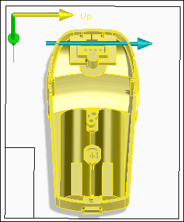 | |||||
7. | Place your views in the viewport, as shown in the image below. 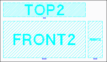 | |||||
8. | Right-click bottom_case in the Drawing Browser and choose Update all Views to update your drawing. | |||||
| ||||||
9. | Select the Front View and click | |||||
10. | Select a section of the front view as shown in the video. Zoom in to get a better view of the section and zoom out after selecting the section. | |||||
11. | Middle-click and then place the detailed view in the viewport. | |||||
12. | Select the detailed view and click | |||||
13. | Select the detailed view and click | |||||
1. |  | |||
2. |  | Create Radius dimensions as shown in the video: select an area of the detailed view or select the arcs or circles. | ||
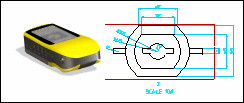
3. |  | Create Single dimensions: select each vertex for the dimension, drag the dimension, and place it near the view, as shown in the image below. 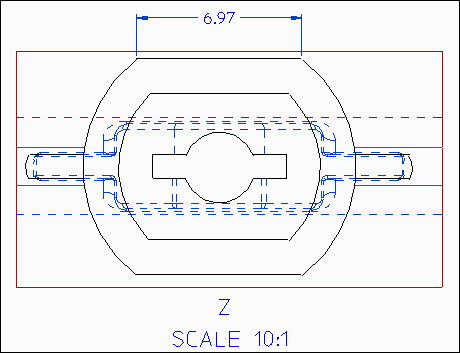 | ||
| ||||
4. | Return to Creo Elements/Direct Modeling: click Applications and then, in the Base group, click Modeling. | |||
