
1. |  | |||
2. | Click > and open a DXF, DWG, or MI drawing.
Click here to download the files for this project. The above video uses handle.dwg. Creo Elements/Direct Annotation automatically opens. | |||
3. | Click | |||
4. |  | Create three Single dimensions and a Chamfer dimension. For Single dimensions, select each vertex for the dimension, drag the dimension, and place it near the view. For the Chamfer dimension, select the chamfer, drag the dimension, and place it near the view, as shown in the image below.  | ||
| ||||
5. | Click the Geometry tab and then, in the Clipboard group, click  Copy and select the Front1 view in the viewport to copy the front view. Copy and select the Front1 view in the viewport to copy the front view. | |||
6. | Click the Applications tab and then, in the Base group, click Modeling to start Creo Elements/Direct Modeling. | |||
7. | Click the View tab and then, in the Window group, click the arrow next to  Clipboard. Click Clipboard. Click  to paste the copied front view on a workplane. to paste the copied front view on a workplane. | |||
8. | Delete unwanted lines and circles on the profile. | |||
Don't forget to click  to complete each operation. to complete each operation. Rotate, Rotate, pan, pan, or zoom for a better view. or zoom for a better view. |
Shortcuts:    |
1. |  | |
2. | Select the border of the workplane, then retain the main body area on the profile and cancel the selection of other areas as shown in the image below. To select or deselect, just click the profile area. 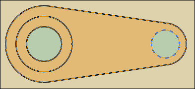 | |
3. | Pull the selected area of the profile (width: 11 units) as shown in the image below. 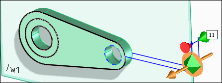 | |
4. | Select the border of the workplane and select only the first (smaller) boss area on the profile as shown in the image below. 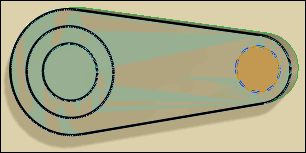 | |
5. | Pull the selected area of the profile. The width of the boss must be measured from the outer edge. The width of the boss is currently measured from the inner edge as shown in the image below. 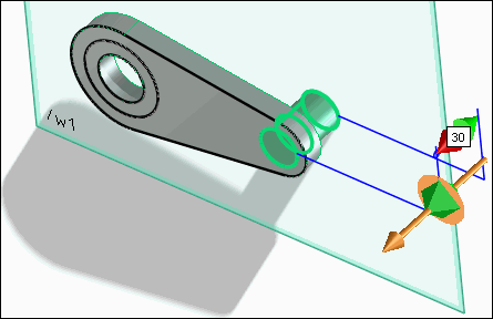 | |
6. | Select the fixed reference (red anchor), place it on the outer edge, and pull the boss (width: 18 units) as shown in the image below. 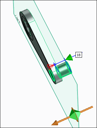 | |
7. | Select the border of the workplane and select only the second (larger) boss area on the profile as shown in the image below. 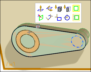 | |
8. | Pull the selected area of the profile (width: 18 units) as shown in the image below. 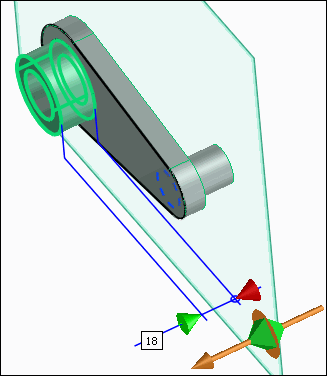 | |
9. | Select the outer edge of the boss and click 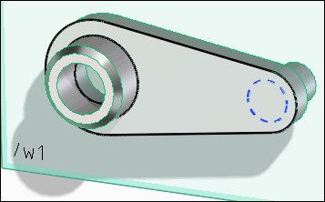 |
