The Mate Align positioning method can be used to move objects in relation to other objects. The parts or assemblies become constrained by each mate or align step.
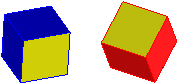
For example, lets say we want to match the yellow faces on these cubes:
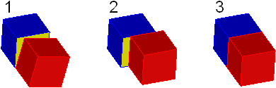
1. First, we Mate the yellow faces. The Mate option positions faces so they lie in opposing directions on the same plane.
2. Now we Align the top faces. The Align option positions faces so they lie on the same side of a plane, as shown.
3. Finally, we align the side faces.
To mate or align parts or assemblies,
1. Click Structure and then, in the Part & Assembly group, click the arrow next to Position.
2. Click Align, Align Axis, or Mate as the type of the positioning operation. The Position dialog box opens with Mate Align selected in the Methods section.
3. Select from the following options:
◦ Mate: Mates the faces, edges, or vertices together.
◦ Parallel: Makes the specified faces or edges parallel.
◦ Align: Aligns two faces, edges, or vertices along the same plane.
◦ Align Axis: Aligns the specified axes.
◦ Offset: Offsets the elements by the specified amount when you select Mate or Align.
◦ Reverse: Reverses the normal direction when you select Mate, Align, or Parallel.
◦ Clear All: Clears all options currently defined in this section of the dialog. Previously moved objects remain at their current positions.
◦ Keep in Active R-Set: Creates a new relation in the active relation set based on a Mate or Align operation.
 Position.
 to complete the operation.