Example: Positioning a part by aligning faces
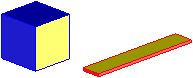
In this example, you will position the red part by aligning its yellow face with the yellow face on the blue cube.
1. Click
Part & Assy 
.
2. Click Position in the Modify section.
3. Click Mate Align. Creo Elements/Direct Modeling displays the positioning options.
4. Click Align.
5. Select face 2 as the face to be moved.
6. Select face 3 as the fixed face.
7. Click
OK
to complete the operation.
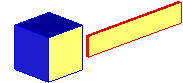
The two faces should lie in the same plane, with the normals of both faces pointing in the same direction, like this: