Shelling removes material from inside a part. You can shell a part by specifying one or more faces. Creo Elements/Direct Modeling removes material from inside the part to leave a thin-walled part. By specifying a negative wall thickness, material can be added to the outside of a part.
As an option, you can specify additional faces (Suppress Features). These features are suppressed so they will not be included on the new faces of the shelled part. Use the Suppress Features option when geometric features (such as ribs or pockets) are thinner than the requested thickness and would hinder the shell creation.
If the shelling operation will result in a corrupt part, Creo Elements/Direct Modeling will create a face part instead of changing the part itself. As the face part reflects the changes you requested, you can use the face part to investigate the cause of the problem, or modify the face part as required.
The figure shows an example of a shelling operation with face 1 being the defined face:
Instead of a part, you can shell faces or recognized features of any model by any distance (offset) using the Shell Faces command. You can modify an already shelled part by first adding a feature such as a boss and then using the Shell Faces command to shell the faces of the added feature.
When you shell a set of faces, which contains blends, Creo Elements/Direct Modeling first calculates the offset without some blends and then re-applies them. These blends are detected automatically.
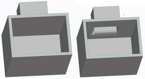
The following example shows a blended boss (feature) shelled using the Shell Faces command.
The shelling operation may fail if:
• One or more faces adjacent to the open face is tangential.
• The part has a vertex with more than four edges.
To shell a part,
1. Click Modeling and then, in the Model group, click the arrow next to Shell.
2. Click Part. The Shell Part dialog box opens.
3. Click Part in the Shell dialog box and select the part in the viewport or structure browser.
4. In the Offset box, type the wall thickness.
5. Click OpenFace and select the face or list of faces you want open. You can click the OpenFace check box to make Open Face mandatory. If you do so, you can directly select a face. Clear the OpenFace check box to make Open Face optional.
6. If necessary, select an option from the Keep Blend list to specify which blends to suppress during the offset calculation.
7. Click Keep Core to retain the shelled out volume as a new part.
8. Click Keep Feats to copy features (abstract features such as Face Set Features or Labels ) attached to the object to the shelled face or the core. If Keep Feats is not clicked, no features except blends and colors are copied to the shelled face or core.
9. Click Suppress Features to specify the faces (geometrical features) that should not be on the shelled part.
10. Click Preview to see the impact of changes before accepting them.
11. Click to complete the operation.
The following list describes each of the options:
• Part: Specifies the name for the part to be machined. You can also use the browser (Browser) to specify the part. The default is the active part.
• Offset: Value for the wall thickness. This value can be negative (to add material to the outside of the part).
• OpenFace: Specifies the open face or faces of the shelled part.
• Keep Blend: Specifies how Creo Elements/Direct Modeling deals with blends in a shell operation; see below.
• Suppress Features: (optional) Specifies a selection of faces which are not to be on the shelled part. When clicked, two options appear. Selecting From Inner suppresses the inner face on the shelled part. Selecting From Outer suppresses the outer face on the shelled part. The check boxes can be used to suppress or retain the faces on the shelled part.
• Chk & Fix: Checks the result and resolves interferences between faces.
• Keep Core: (optional) Tells Creo Elements/Direct Modeling to keep the mold (the part that is shelled out). You can then work on this mold as a separate part.
• Keep Feats: Copies features to the shelled face and the core. If Keep Feats is not clicked, only the blends and colors are copied to the shelled face and the core.
The value for the offset must be greater than the part's accuracy (geometric resolution). For example, if the part's accuracy is 1.0E-4, you cannot specify an offset of 1.0E-5. Creo Elements/Direct Modeling displays an error message if the value for the offset is too small or too large.
Creo Elements/Direct Modeling adjusts resolutions for separate parts and workplanes. If the blank part's resolution is finer, you must confirm the resolution change. If the resolution of the blank part is coarser, and does not need the resolution change, the resolution for the other part is automatically changed. The resulting resolution will be the lowest resolution of the parts/workplane involved.
When you shell a part containing blends, Creo Elements/Direct Modeling first calculates the offset without some blends and then re-applies them. These blends are normally detected automatically. However, if you encounter problems while creating the shelled part, the Keep Blend setting provides you with more control over which blends to suppress during the offset calculation. The three options are the following:
• Auto: Creo Elements/Direct Modeling suppresses freeform blends, variable radius blends, blends smaller than the shell distance, and their dependent blends. The Auto setting is recommended for most shell operations.
• None: Creo Elements/Direct Modeling avoids suppressing blends for the offset calculation. This option is useful when the blends are too complex to be suppressed or could not be created on the offset part. (Note that None is only recommended for part resolutions of 1.0E-4 mm or coarser.)
• All: Creo Elements/Direct Modeling suppresses all blends when calculating the offset. This option is useful when a portion of a blend face would become self-intersecting or would vanish in the offset part.
To shell a face or recognized feature,
1. Click Modeling and then, in the Model group, click the arrow next to Shell.
2. Click Faces. The Shell Faces dialog box opens.
3. Click Faces in the Shell Faces dialog box and select a face in the viewport or click Rec.Feat in the Shell Faces dialog box and select a recognized feature in the viewport.
You can shell faces that do not form a geometric feature, but most of the geometry in the output can be lost.
4. In the Offset box, type the wall thickness.
5. Click Preview to see the impact of changes before accepting them.
6. Click Next to finish the operation and shell another set of faces.
7. Click Chk & Fix to check the result and resolve interferences between faces.
8. Click to complete the operation.
Limitation
You can only shell a connected set of faces that has no holes. Especially, you cannot shell multiple features at the same time.
 to complete the operation.
 Faces. The Shell Faces dialog box opens.