In this example you will pull a profile in the active workplane (w1), projected from an existing part p1, to a plane which is defined as the normal to one of the faces of the original part. The profile is pulled until it intersects the defined plane.
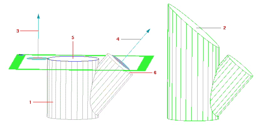
The figure below shows the original part (1), the workplane containing the profile to be pulled, and the resulting part (2).
After creating the original part and positioning a workplane parallel to the face shown in the figure above:
1. Click Modeling and then, in the Draw group, click the arrow next to Project.
2. Click Face under Project Geometry.
3. Click face 5 shown in the figure above. Creo Elements/Direct Modeling projects the circumference of the face to create a 2D profile in the workplane.
4. Click Modeling and then, in the Model group, click the arrow next to Pull.
5. Click Pull Linear. The Pull dialog box opens. Part is set to the active part p1 and Workplane is set to the active workplane containing the profile w1.
6. In the Type box, select To Plane.
7. Use the Axis 3D tool to define the target plane as the normal to face 6 in the figure above. You will see the feedback arrow (4) showing the orientation of the plane. Creo Elements/Direct Modeling displays the defined target plane in the field next to To Plane.
8. Define the pull direction by choosing the option in the Direction box that shows a feedback arrow (3) pointing in the direction of the target plane.
9. Clear Keep WP. Keep Prof is automatically disabled.
10. Click to complete the operation. Creo Elements/Direct Modeling pulls the profile to the target plane and creates the new part.
 Project.
 Face under Project Geometry.
 to complete the operation. Creo Elements/Direct Modeling pulls the profile to the target plane and creates the new part.