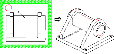
In this example you will imprint the silhouette of a view of part 1 from the active workplane (w1). Shown below are part 1, w1, and the result of imprinting the silhouette onto part 1.
After creating the workplane and the part:
1. Click Modeling and then, in the Model group, click the arrow next to Imprint.
2. Click Silhouette. The Silhouette dialog box opens. Part is set to /p1 (the active part) and the workplane is set to w1 (the active workplane). You do not need to change the workplane or the part.
3. Click Direction.
4. Click W (in Direction 3D menu). The Direction entry box displays Defined.
5. Click to complete the operation.
Creo Elements/Direct Modeling imprints the silhouette of the chosen view onto part 1.
To remove part 2 from the current view and view the imprint:
1. Open the Drawlist.
2. Click the check button off to the left of /p2's icon.
Remove Workplane w1 for clarity.
Rotate part 1 with the Dynamic control to view the edges of the silhouette on part 1.
 Imprint.
 Silhouette. The Silhouette dialog box opens. Part is set to /p1 (the active part) and the workplane is set to w1 (the active workplane). You do not need to change the workplane or the part.
 to complete the operation.