The Rectangle command in the Create 2D menu provides visual feedback with information such as length of the two sides of the rectangle.
• When you draw a rectangle, you can select two points in the viewport or on a workplane to set the line which connects the two points as a mirror. For more information, see
Set a mirror for 2D geometrical elements.
• For information about highlighting intersecting elements, see
Draw a line or an arc.
To draw a rectangle,
1. Click Modeling and then, in the Draw group, click the arrow next to Rectangle.
2. Click Rectangle.
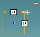
3. Click a point in the viewport to mark the first corner of the rectangle. You can also type the coordinate and press ENTER.
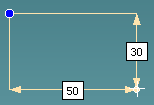
4. Move the cursor to see the feedback for the rectangle, as shown below:
Alternatively, you can type values for the two sides of a rectangle and press TAB or SHIFT+TAB to toggle the cursor between the two values:
• Press TAB, type a value for the width of the rectangle, and press ENTER.
• Type a value for the height of the rectangle and press ENTER to complete the rectangle.
5. Click anywhere in the viewport to complete the rectangle. Alternatively, you can type the coordinate of the second point and press ENTER to complete the rectangle.
You can use the Linear Bisector or the Angular Bisector command (on-the-fly) when you draw a rectangle; for example, to find the midpoint of a side of a rectangle.
• To use a linear bisector:
◦ Press X or,
◦ Right-click and choose Linear Bisector on the context menu or,
◦ Press SPACEBAR or the assigned key and click on the Option Mini Toolbar (OMT).
• To use an angular bisector:
◦ Press Y or,
◦ Right-click and choose Angular Bisector on the context menu or,
◦ Press SPACEBAR or the assigned key and click on the OMT.
You can use the Line Between 2 Points command (on-the-fly) to create a temporary line and then use the midpoint of this line as a reference to draw rectangles; for example, you can draw a rectangle using the midpoints of the diagonals of two other rectangles.
To create a temporary reference line between two points:
a. Press M, or right-click in the viewport and choose Line Between 2 Points on the context menu.
Alternatively, press SPACEBAR or the assigned key and click on the OMT.
b. Select any two points on the viewport.
6. Draw as many rectangles as desired.
7. Click to complete the operation.
You can also draw a rectangle using (Central), Central U, or Central V.
To draw a rectangle using (Central), Central U, or Central V,
1. Click Modeling and then, in the Draw group, click the arrow next to Rectangle.
2. Click one of the following:
◦ Central
◦ Central U
◦ Central V
If the Rectangle command is active, you can also:
• Right-click the viewport and select Central, Central U, or Central V from the context menu.
• Press the SPACEBAR (or the assigned key) to open the Option Mini Toolbar (OMT) and click one of the following:
◦ (Central)
◦ (Central U)
◦ (Central V)
3. Select a point in the viewport. You can also type the coordinates and press Enter to select the first point.
4. Draw a rectangle using one of the following methods:
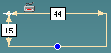
◦ (Central): Move the cursor to draw a rectangle with the selected (first) point as the central point as shown in the following image.
◦ (Central U): Move the cursor to draw a rectangle with the selected (first) point as the center along the U direction.
◦ (Central V): Move the cursor to draw a rectangle with the selected point as the center along the V direction.
You can also type values for the two sides of the rectangle and press TAB or SHIFT+TAB to toggle the cursor between the two values:
• Press TAB, type a value for the width of the rectangle, and press ENTER to set the width of the rectangle. To change the set width, press TAB twice and press F.
• Press TAB, type a value for the height of the rectangle, and press ENTER to set the height of the rectangle. To change the height, press TAB twice and press F.
5. Select a point in the viewport to complete the rectangle.
You can use the Linear Bisector or the Angular Bisector command (on-the-fly) when you draw a rectangle; for example, to find the midpoint of a side of a rectangle.
• To use a linear bisector:
◦ Press X or,
◦ Right-click and choose Linear Bisector on the context menu or,
◦ Press SPACEBAR or the assigned key and click on the Option Mini Toolbar (OMT).
• To use an angular bisector:
◦ Press Y or,
◦ Right-click and choose Angular Bisector on the context menu or,
◦ Press SPACEBAR or the assigned key and click on the OMT.
You can use the Line Between 2 Points command (on-the-fly) to create a temporary line and then use the midpoint of this line as a reference to draw rectangles; for example, you can draw a rectangle using the midpoints of the diagonals of two other rectangles.
To create a temporary reference line between two points:
a. Press M, or right-click in the viewport and choose Line Between 2 Points on the context menu.
Alternatively, press SPACEBAR or the assigned key and click on the OMT.
b. Select any two points on the viewport.
6. Draw as many rectangles as desired.
7. Click to complete the operation.
You can also draw a rectangle at a specific angle to the X-axis using the Slant option.
To draw a rectangle using the Slant option,
1. Click Modeling and then, in the Draw group, click the arrow next to Rectangle.
2. Click Slant.
3. Select a point in the viewport. You can also type the coordinates and press ENTER to select the first point.
4. Move the cursor to draw a line at any angle to the horizontal X-axis in the viewport.
You can also right-click the viewport and select Set Angle from the context menu, type the angle, and press ENTER to draw the line segment at an angle to the X-axis.
5. Click another point to complete the line segment. You can also type the coordinates for the second point and press ENTER to complete the line segment.
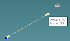
You can also right-click the viewport and select Set Length from the context menu, type the length, and press ENTER to set the length of the line segment.
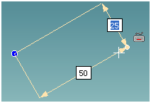
The length of the line drawn is taken as the width of the rectangle. In the example shown below, the line segment of length 50 units is drawn at an angle of 30 degrees to the X-axis.
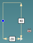
6. Move the cursor to draw a rectangle as shown in the following image.
The height of the rectangle is highlighted as you move the cursor.
You can also type values for the two sides of the rectangle and press TAB or SHIFT+TAB to toggle the cursor between the two values:
• Press TAB, type a value for the width of the rectangle, and press ENTER to set the width of the rectangle. To change the set width, press TAB twice and press F.
• Press TAB, type a value for the height of the rectangle, and press ENTER to set the height of the rectangle. To change the height, press TAB twice and press F.
7. Click the desired point in the viewport to complete the rectangle.
You can use the Linear Bisector or the Angular Bisector command (on-the-fly) when you draw a rectangle; for example, to find the midpoint of a side of a rectangle.
• To use a linear bisector:
◦ Press X or,
◦ Right-click and choose Linear Bisector on the context menu or,
◦ Press SPACEBAR or the assigned key and click on the Option Mini Toolbar (OMT).
• To use an angular bisector:
◦ Press Y or,
◦ Right-click and choose Angular Bisector on the context menu or,
◦ Press SPACEBAR or the assigned key and click on the OMT.
You can use the Line Between 2 Points command (on-the-fly) to create a temporary line and then use the midpoint of this line as a reference to draw rectangles; for example, you can draw a rectangle using the midpoints of the diagonals of two other rectangles.
To create a temporary reference line between two points:
a. Press M, or right-click in the viewport and choose Line Between 2 Points on the context menu.
Alternatively, press SPACEBAR or the assigned key and click on the OMT.

 on the Option Mini Toolbar (OMT).
 on the OMT.
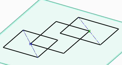
 on the OMT.
 to complete the operation.
 (Central), Central U, or Central V.