Use projection from 3D or 2D geometry to create 2D geometry
When you draw a line, arc, rectangle, circle, or any other 2D element, you can use the projected lines from the 3D geometry in the viewport.
When you draw a 2D element, the 2D CoPilot:
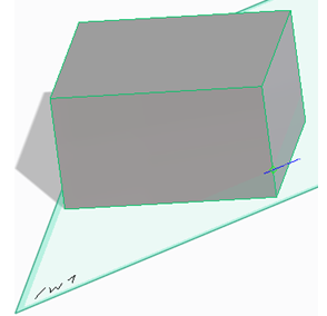
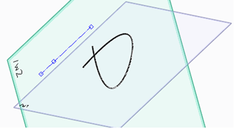
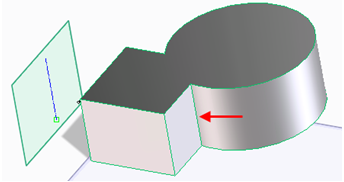
• Projects a straight edge (3D geometry) onto an active workplane, which is parallel to the straight edge.
◦ The straight edge is projected as a blue line and the vertices are projected as green squares onto the active workplane as shown in the following image.
◦ Projects an intersection of a straight edge and the workplane as a vertex onto the workplane as shown in the following image.
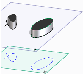
• Projects a circular edge or an arc edge (3D geometry) onto an active workplane, which is parallel (not in the same plane) or perpendicular to the circular edge.
◦ The circular edge is projected as a blue circle and the center of the edge is projected as a blue cross onto the parallel workplane.
◦ The circular edge is projected as a blue line, the center of the edge is projected as a green cross, and the vertex is projected as a square or a diamond onto the perpendicular workplane. The end points of the projected lines are diamond-shaped.
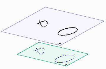
• Projects the center of the circular edge onto an active workplane, which is parallel, perpendicular, or oblique to the circular edge. The center is projected as a cross and the circular edge is projected as an ellipse onto the oblique workplane as shown in the following image.
• Projects a 2D spline and a 2D ellipse onto a parallel workplane as a blue spline and a blue ellipse, respectively.
To project 2D geometry elements, click
All Workplanes in the 2D CoPilot Settings.
• Projects a 2D spline onto a perpendicular workplane as a blue line.
• Projects a spline edge and an elliptical edge onto a parallel workplane as a blue spline and a blue ellipse, respectively.
• Projects an edge, which is formed by intersecting surfaces, in the blue color. The following image shows the projected edge on a parallel workplane.
You can change the color of the projected lines in the 2D CoPilot Settings dialog box. See
Change 2D CoPilot settings.
You can use the lines and vertices projected by 3D geometry as references to draw 2D geometry. The following example shows how you can use the projection of a circular edge to draw a circle.
To draw a circle using a projection of the center of a 3D circular edge:
1. Click Modeling and then, in the Draw group, click the arrow next to Circle.
2. Click Center & Radius.
3. Move the cursor over the circular edge in the viewport. The circular edge is projected as a blue circle and the center of the edge is projected as a cross onto the active parallel workplane.
4. Select the cross on the workplane and move the cursor to draw a circle.
5. Click to complete the operation.
Change projected geometry to construction geometry
The 2D geometrical elements that are projected from the 3D geometry are temporary. You can change the projected 2D geometrical elements to construction geometry and use the construction geometry to create 2D geometry.
You can project intersecting 2D splines onto a parallel workplane and change the projected geometrical elements to construction geometry as shown in the following image.
To change projected geometry to construction geometry:
• Press SPACEBAR or any other assigned key and click on the Option Mini Toolbar (OMT) or,
• Right-click the viewport and select 3D Project to Construct on the context menu.
To undo the conversion of projected geometry to construction geometry,
1. Click the arrow next to (Undo) on the Quick Access Toolbar.
2. Click Undo One to remove the construction geometry.
Limitations
• The projected 3D vertices are not converted to construction geometry.
• The construction lines cannot be changed back to projected lines.
 Circle.
 to complete the operation.
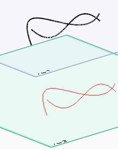
 on the Option Mini Toolbar (OMT) or,
 (Undo) on the Quick Access Toolbar.