You can create vertical, horizontal, and other construction lines with the 2 Pos, Parallel to, Cross, Bisector, and Angle Sector commands.
The following commands will get you started; follow the instructions on the status bar to use other commands.
• When you draw construction lines, lines, or arcs with 2D CoPilot support, the cursor snaps to the existing elements in the viewport and you can use 2D CoPilot features such as
Measure Relative. All construction line commands are supported by the 2D CoPilot.
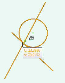
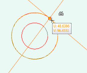
• When you draw 2D elements with 2D CoPilot support, the cursor snaps to intersection points and the intersecting elements are highlighted in the viewport as shown in the following image.
To draw an infinite line (construction only),
1. Click Modeling and then, in the Draw group, click the arrow next to (Infinite Construction 2 Pos).
2. Click 2 Points.
3. Click a point in the workplane for the start location of the line.
4. Click a point in the workplane for the end location of the line.
5. You can create as many construction lines as you want before you close the operation.
1. Click Modeling and then, in the Draw group, click the arrow next to (Infinite Construction 2 Pos).
2. Click Horizontal.
3. Select a point on the workplane to draw a horizontal construction line.
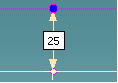
When you draw a horizontal construction line relative to a circle using
Measure Relative, the distance from the circle is measured from the closest point on the circumference of the circle.
4. Create additional construction lines, if required.
5. Click to complete the operation.
To draw a vertical construction line,
1. Click Modeling and then, in the Draw group, click the arrow next to (Infinite Construction 2 Pos).
2. Click Vertical.
3. Select a point on the workplane to draw a vertical construction line.
When you draw a vertical construction line relative to a circle using
Measure Relative, the distance from the circle is measured from the closest point on the circumference of the circle.
4. Create additional vertical construction lines, if required.
5. Click to complete the operation.
To draw a parallel line (construction only),
1. Click Modeling and then, in the Draw group, click the arrow next to (Infinite Construction 2 Pos).
2. Click Parallel.
3. Select the line or any 2D element to which you want to draw a parallel construction line or follow the prompt and enter one or more offsets first.
4. If a reference line is selected first without giving any offsets, move the cursor away and the 2D Copilot shows the distance from the selected line. You can also type a distance and press ENTER to create the parallel line.
5. Create additional parallel construction lines, if required.
6. Click to complete the operation.
To draw a cross (construction only),
1. Click Modeling and then, in the Draw group, click the arrow next to (Infinite Construction 2 Pos).
2. Click Cross.
3. Enter 2D coordinates or click any point on the workplane. The 2D Copilot helps you find a center point, midpoint, vertex, or an intersection point on the existing geometry.
4. Create additional cross-lines (construction lines), if required.
1. Click Modeling and then, in the Draw group, click the arrow next to (Infinite Construction 2 Pos).
2. Click Bisector.
3. Click any point. The 2D Copilot helps you find a center point, midpoint, vertex, or an intersection point on the existing geometry. You can see a visual feedback between the first point you clicked and the cursor.
By default, the fraction value is 0.5. You will see a sector at the midpoint of line joining the first point and the cursor. At any step, you can type a different fraction value and press ENTER. For values between 0 and 1, the sector will be between the reference positions, for values less than 0 the sector will be before the first reference position, and for values greater than 1 the sector will be after the second reference position or cursor point.
4. Click the second point. A bisector line is drawn at the midpoint (assuming a fraction value of 0.5) and perpendicular to the two points you clicked.
5. Create additional bisector construction lines, if required.
6. Click to complete the operation.
To draw an angle bisector (construction only),
1. Click Modeling and then, in the Draw group, click the arrow next to (2 Points.
2. Click Angle Sector.
3. Enter a different fraction value. If no value is entered, the default value (0.5) will be used for creating the angle bisector.
By default, the fraction value for an angle bisector is 0.5. You can type a different fraction value and press ENTER. For values between 0 and 1, the angle bisector will be between the reference positions, for values less than 0 the angle bisector will be before the first reference position, and for values greater than 1 the angle bisector will be after the second reference position or cursor point.
4. Click the apex of an angle. The 2D Copilot helps you to find the apex.
5. Select a reference point to determine the baseline of the angle. The feedback shows you the angle value. You can also type a reference angle and press ENTER.
6. Move the cursor away from the baseline of the angle. You will see the angle bisector feedback between the reference point and the cursor.
7. Select the second reference point. The feedback shows you the angle. You can also type the second reference angle and press ENTER. An angle bisector line is drawn from the apex, bisecting the angle.
Type a positive value to orient the second reference angle in the direction of movement of the cursor. Type a negative angle to flip the direction.
8. Create additional angle bisector construction lines, if required.
9. Click to complete the operation.
When the 2D CoPilot is active, press SPACEBAR to open the Option Mini Toolbar (OMT) and select Geometry or Construction in the box to change the drawing mode.
 (
( to complete the operation.
 Horizontal
 Vertical