Functional Dependency Gate
The functional dependency gate is used to indicate that all dependent events are forced to occur in a particular order when the trigger event occurs. The separate occurrence of any of the dependent events has no effect on the trigger event. The functional dependency gate has one trigger event and can have one or more dependent events.

Dependent events are repeated events that are present in other parts of the fault tree. Dependent events are either basic events or spare events. The trigger event can be a terminal event or outputs of any AND, OR, or dynamic gate. Generally, the output of a functional dependency gate is not that important; however, it is equivalent to the status of its trigger event.
The functional dependency gate can also be used to set the priorities for spare gates. For example, if multiple spares are connected to this type of gate, after the occurrence of the trigger event, all spares that are connected to the functional dependency gate fail.
Upon failure of these spares, the next available good spares in these spare gates replace the failed spares. If a conflict exists choosing the next available spare between multiple spare gates, the priority is based on the order of the connection of these spares in the functional dependency gate from left to right.
You can rearrange the dependent events that enter functional dependency gates by clicking and dragging them to new locations.
Summary of Logic: When the trigger event is TRUE, then dependent events are forced to become TRUE. The trigger event must be TRUE for the output to be TRUE.
A truth table for a functional dependency gate follows.
Trigger | Output | Dependent Event A | Dependent Event B |
|---|---|---|---|
T | T | T | T |
F | F | T/F | T/F |
Example
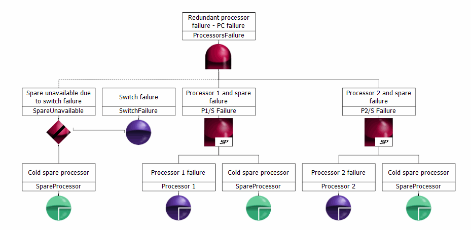
A computer system has dual redundant processors. Assume that a cold spare can replace either processor, and the cold spare is assumed to not fail before it is required. It is possible that the failure of the switching mechanism would prevent its use.
In the following figure, the spare events, Cold spare processor, are shown in green because they are all the same spare. The connector from the functional dependency gate to its parent gate is a dashed line because > gate outputs is selected in the Project properties. When this is the case, outputs of functional dependency gates are not considered inputs of their parent gate. For more information, see FTA Project Properties.
Here a computer system failure is due to the failure of the dual redundant processors when both processors and their spare fail. Because we assumed that the spare would not fail when not in use, a cause for the spare failure before it is in use would be the trigger event, which is the failure of the switching mechanism. Once in use, the spare itself could fail and would also be considered to be failed if the switching mechanism fails when the spare is in use.
