Fault Tree Construction
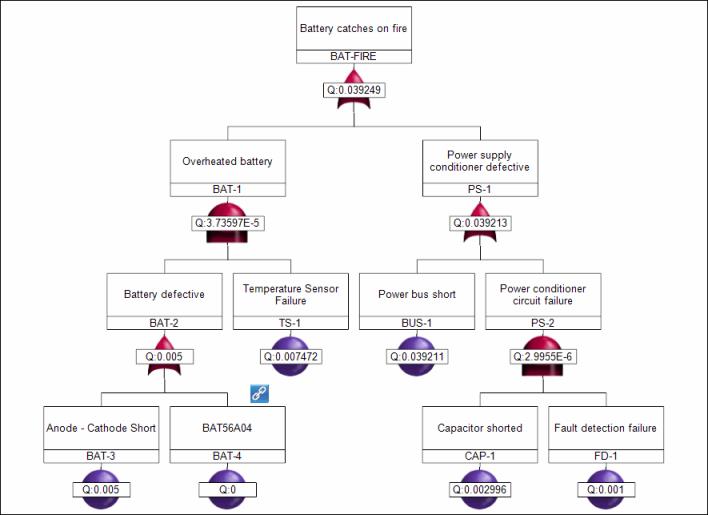
Fault trees provide a convenient, symbolic representation of system failure. The tree diagram represents the relationship between lower-level events (such as hardware failures, software failures, and human errors) and the specific undesirable event at the system level (top event). Different combinations of lower-level events can result in the occurrence of the top event.
Gates represent the Boolean logic operators that link various branches of the tree together and determine whether the top event can occur. The lowest-level events in each tree branch are generally referred to as basic events, though they are sometimes called terminal events or primary events. Specified event and gate properties fare shown in rectangular text boxes above their symbols. The FTA module supports many different types of events and gates. For more information, see Events and Gates.

To build a fault tree, you perform the following steps:
1. Identify the top event.
2. Identify the first-level events.
3. Link the first-level events to the top event using gates.
4. Identify the second-level events.
5. Link the second-level events to the top event using gates.
6. Continue to repeat these steps as necessary for all subsequent levels of events.
While a manager might need a tree to have only a few levels, a scientist might need a tree to have many levels, perhaps going down far enough to analyze chemical reactions. A good rule of thumb is to develop the tree down to the level at which you can exert reasonable control.
For example, if you are analyzing a safe-arm system that involves a programmable controller, you probably do not have to develop causes for controller malfunction as part of your analysis. You can simply assume that the controller can malfunction and then analyze the rest of the system to ensure that controls or barriers prevent inadvertent firing of the circuit if the controller does malfunction. If your system has line replaceable units (LRUs), you should probably stop at the LRU level.
When building a tree, it is important that events and conditions are consistently named. The same name must be used for the same event or condition throughout the fault tree. In the description of the event, you want to indicate not only what could fail but also how it could fail. For example, the description for a switch failure might be Switch Sw-418 contacts fail closed.
Also, be sure to take advantage of a fault tree’s greatest benefit: the ability to include more than just hardware failures. A fault tree can include events caused by operator errors, design flaws, software failures, environmental influences, and undesired interactions. You do not want your tree to focus only on component failures or limit your analysis by breaking the tree into subsystems such as Electrical and Mechanical failures. When possible, make event identification a team effort.
If you are using both the FTA and FMEA modules, you can build a fault tree from a completed FMEA from either module. For more information, see Building a Fault Tree from a FMEA. |