Using Autodesk Inventor BOM with Windchill
Beginning at Windchill 10.2 M010, Windchill Workgroup Manager supports the following Autodesk Inventor features so that the resulting WTPart structure correctly represents the BOM in Autodesk Inventor:
• Phantom Assembly
• References
• Item number in Inventor BOM
Phantom Assemblies
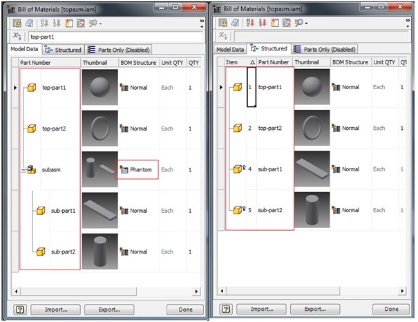
• When a subassembly is set to Phantom, the phantom node is not shown in the Autodesk Inventor Structured BOM, and the sub-components are rolled up to the next level. This has no effect on the “Parts Only” BOM, since that BOM only shows a flats parts list, i.e., assemblies are not shown.
• When a part is set to Phantom, it has the same effect as setting it to a reference, i.e., the part is not shown in the BOM.
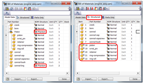
• Windchill supports the concept of Phantom assemblies beginning at Windchill X-20. The WTPart structure will hide Phantom assemblies and roll up the sub-components to the next level in the BOM. If you set a part or assembly to Phantom in one assembly, it will appear as a Phantom in all assemblies. This function is controlled by the Site level preference Phantom Assembly Override Attribute Name, and should be set with a value of any Boolean attribute valid for Autodesk Inventor.
Use Case — The Boolean attribute (in this case, PHANTOM) is created and added to > in Type and Attribute Management.

Assume the following BOM structure:
topasm
|__top-part1
|__ top-part2
|_subasm (marked as Phantom)
|_sub-part1
|_ sub-part2
|__top-part1
|__ top-part2
|_subasm (marked as Phantom)
|_sub-part1
|_ sub-part2
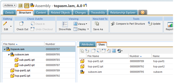
After performing Check In with Auto-associate, WTParts will be created for all CAD Documents. The top assembly WTPart Structure and Uses tabs will appear as shown.
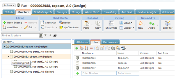
The WTPart for the Phantom assembly ‘subasm’ will still be shown in the ‘topasm’ structure with the icon and tooltip Gathering Part as shown. However, the Workspace listing page will show the normal icon for the phantom assembly ‘subasm’. Thus, the WTPart structure in the Windchill BOM will appear the same in Autodesk Inventor (with the accepted behavior of WTPart for the Phantom assembly still shown in the Structure, but with the Gathering Part icon and tooltip). The CAD Document structure for the ‘topasm’ will not show the effect of the above, and will appear as shown.
References
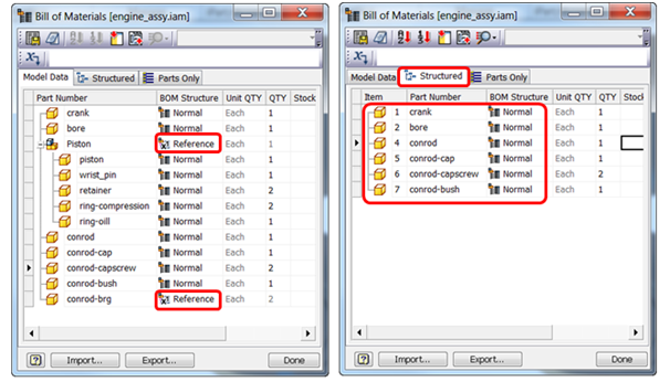
• When a subassembly is set to Reference, neither the assembly nor its sub-components are shown in either the “Structured” or “Parts Only” BOM.
• When a component is set to Reference, the component is not shown in the BOM.
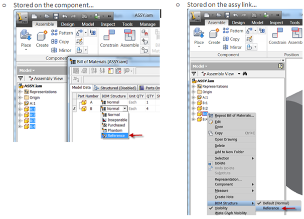
• Autodesk Inventor supports two variations of “Reference” BOM parts. The “Reference” information can be either “stored on the component” or “stored on the assembly link” as shown.
When the Reference information is “stored on the component” (i.e., a component is flagged as Phantom/Reference in the Model Data/Structured tab), the BOM tab for that component, when navigated to from > > will also have the flag applied — in this case, ‘refsubasm’ is marked as Reference in the Model tab in the BOM table in ‘reftopasm’. The component flagged as Reference is shown set in the refsubasm document on the Bill of Materials tab.
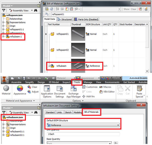
To work with References, you use the preference Part Structure Override Attribute Name, set to a Boolean attribute created in Type and Attribute Management. When the Reference information is to be “stored on the component”, you can add the Boolean attribute in Type and Attribute Management either in > , or in EPM Document Uses Link. However, when the Reference information is to be “stored on the assembly link”, the Boolean attribute is only added in EPM Document Uses Link.
Use Case — Assume the following assembly structure:
reftopasm
|__reftopasm01
|__reftopasm02
|_refsubasm (marked as Reference)
|_refsubasm01
|_refsubasm02
|__reftopasm01
|__reftopasm02
|_refsubasm (marked as Reference)
|_refsubasm01
|_refsubasm02
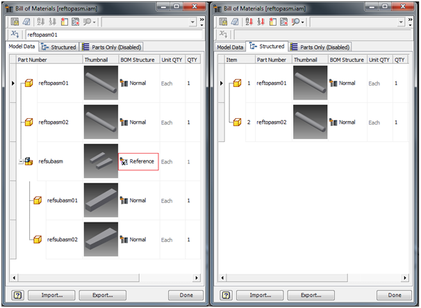
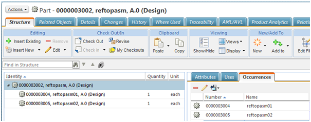
After performing Check In of the top assembly with Auto-associate, WTParts will be created for all CAD Documents. Note that the reference assembly is not displayed in the structure along with its children, and is not present in the Autodesk Inventor BOM. The main assembly WTPart structure will appear as follows.
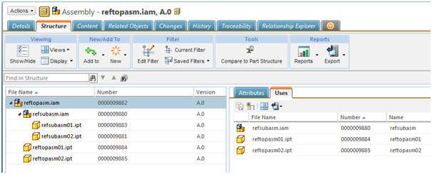
The main CAD assembly structure will not be affected by this, and will display all the components as follows.
Item Number in Autodesk Inventor BOM
Each component in an assembly BOM is allocated an Item Number. These numbers are displayed as ballooned parts lists on drawings, but are stored in the assembly BOM table. Autodesk Inventor BOM Item numbers are sequential numbers allocated to each item in a given assembly BOM. Windchill 10.2 M010 supports the following scenarios related to Item Numbers.
• Map Autodesk Inventor BOM Item Number to Find Number
• Map Autodesk Inventor BOM Item Number to Line Number
• Map Autodesk Inventor BOM Item Number to WTPart Uses Link Attribute
Use of Line Number Attribute and Find Number Attribute Preferences to map Item Number in Autodesk Inventor BOM — Two preferences are available at the Site level to support this functionality: Find Number Attribute and Line Number Attribute.

The Find Number Attribute preference can either have a ‘String’ or an ‘Integer’ attribute mapped to it. The Line Number Attribute preference can only have an ‘Integer’ attribute mapped to it. In addition, another preference, CAD BOM Item Attribute, must be set with the same attribute as that of either of the above two preferences for which the Item Number needs to be propagated.
Use Case of Item Number mapped to Line Number — The Integer attribute LNO is created on the server and added in EPM Document Uses Link. The same attribute is added to the Line Number Attribute preference and the CAD BOM Item Attribute as shown below.


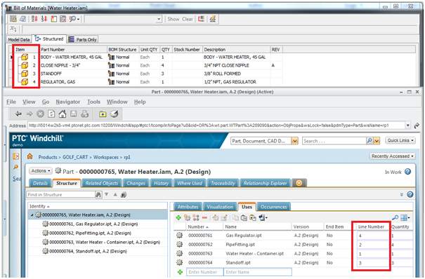
A user has created an assembly as shown below, and the default Item Number on the Structured BOM appears as shown.
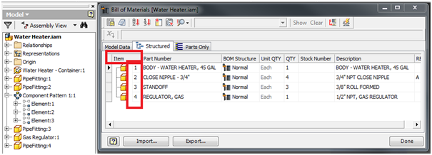
After performing Check In with Auto-associate, WTParts will be created, and the Item Number value will be propagated from the Autodesk Inventor session to the Line Number column on the Assembly WTPart structure Uses tab as shown.
