Use Windchill WTPart product structure for BOM Tables and Position Flags on Annotation drawings
You can transfer a WTPart (Windchill part) Bill of Material (BOM) Report directly to a Creo Elements/Direct Modeling session that is connected to Windchill Workgroup Manager. You can then use the WTPart BOM to draw BOM tables or create position flags on Creo Elements/Direct Modeling Annotation drawings.
You can transfer the following BOM Reports to the Modeling Annotation session:
• Single-Level BOM
• Single-Level BOM with Notes
• Multi-Level BOM
• Multi-Level BOM with Replacements
For more details, refer to Limitations section at the bottom of this page.
The Annotation module has sample BOM Table layouts (WGM-DIN, WGM-ISO, WGM-Custom) that you can customize. You can also customize the list of Windchill BOM attributes that are available for text reference assignment. For more information about customization, see Customizing Windchill BOM Attributes for Text Reference Assignment.
Prerequisites
You need an assembly with WTParts. Use custom check in with the Auto Associate Parts to CAD Documents option to associate the WTParts to the corresponding CAD models in Creo Elements/Direct Modeling. For more information, see Custom Check In.
Transferring a WTPart BOM to a Modeling Annotation session
You must first generate a BOM Report for a WTPart structure and then export it to Annotation.
To generate and then transfer a WTPart BOM Report to a Modeling Annotation session, perform the following steps:
1. In the Windchill Workgroup Manager workspace or Windchill Cabinets (server or commonspace) embedded browser, in the Actions column, click the information icon  for a WTPart (
 assembly or part).
for a WTPart ( assembly or part).Alternatively,
a. Click the information icon for a CAD assembly or part. The information page appears.
for a CAD assembly or part. The information page appears.b. On the Related Objects tab, click for the corresponding WTPart.
for the corresponding WTPart.The information page, which displays the assembly details, structure, related objects, change history, and other information for the WTPart, appears.
On the Uses tab, the table must have the following four columns:
▪ Name
▪ Number
▪ Line Number
▪ Reference Designator
If the active view does not include the Line Number or Reference Designator column by default, add the column to the table using the Manage Table Views command. For information on how to view table columns, see Creating and Editing new Table Views. |

2. You can create either a single-level or multi-level report by performing one of the following actions:
On the information page, on the Structure tab, in the Reports action set,
◦ Click > .
◦ Click > .
◦ Click > .
◦ Click > .
The Single-Level or Multi-Level Bill of Materials Report is generated. The following image shows Multi-Level Bill of Materials Report.

3. To transfer the BOM to Annotation, on the Bill of Materials Report page, click > .

The Current BOM table appears in the active Modeling Annotation session and contains the BOM information sent from Windchill.

• Assemblies with multi-owner links are not supported for BOM transfer. Assemblies must have owner association to their parts. • If Annotation is not active in the connected Modeling session, BOM transfer does not take place and an error occurs as shown below. 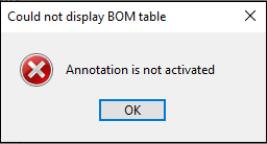 • The related CAD Assembly should be open in session. If it is not open, BOM transfer does not take place and an error occurs as shown below.  |
After you generate and export the BOM report to Creo Elements/Direct Modeling Annotation, you can draw the BOM table sketch and create position flags.
• By default, the reference designator column is included in the view with which BOM report is exported from Windchill. If it is not available, customize the field manually. • Reference designator field must have a value. It should not be empty. • The preference values for these reference designator preferences must be unique in Windchill — Reference Designator Separator Character, Reference Designator Range Character, Reference Designator Begin Escape Character, and Reference Designator End Escape Character. • Avoid using values of the reference designator preferences in the fields where manual entry is required, such as Component Names or Reference Designator fields. • When a WTPart is added manually, a unique name for the reference designator must be added in the parent assembly structure and must not be renamed after the part structure is built. • Avoid renaming the auto generated reference designator values after the part structure is built. • Reference designator field must not be left blank. • Exporting of the BOM report generates error if component names contain characters that are also the values of the Windchill preference Reference Designator Range Character or Reference Designator Separator Character. 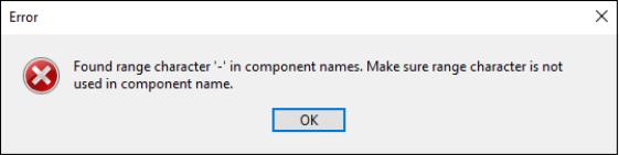 If you continue working by ignoring the error, geometry highlighting will not work. |
Drawing a BOM table sketch
To draw the BOM table sketch in Annotation, perform the following steps:
1. On the Insert tab, in the BOM group, click Draw. The Draw BOM window appears.
2. In the Act. Layout list select one of the following sample BOM Table layouts:
◦ WGM-Custom
◦ WGM-DIN
◦ WGM-ISO
3. Click Draw. The BOM table follows the cursor.
4. Click somewhere in the viewport (graphics area) to place the BOM table sketch. The BOM table sketch displays some standard columns, but you can customize the layout.
The following image shows BOM table sketch generated using Act. Layout as ‘WGM-Custom’.
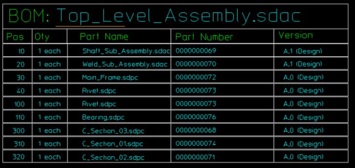
The Pos column in BOM table sketch corresponds to the Line Number column in Current BOM table. For more information on how to draw BOM tables, in the Creo Elements/Direct Modeling help, see Draw a BOM table. |
Creating position flags in Annotation
You can create position flags to identify the geometrical elements corresponding to a selected WTPart.
To create a position flag, perform the following steps:
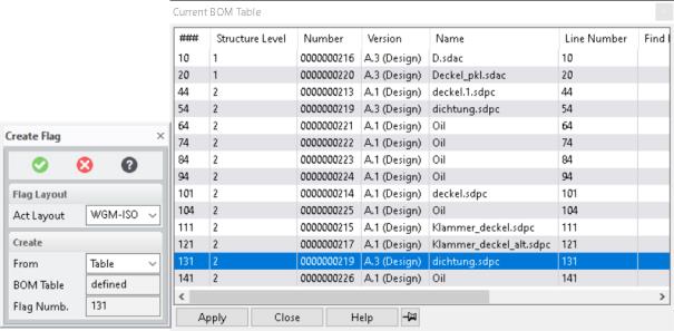
1. Click the arrow next to Pos Flags and then click BOM Flag create. The Create Flag window appears.
2. In the From list, select either Table option or Geometry option.
a. If you selected Table option:
i. The Current BOM Table appears as shown below.
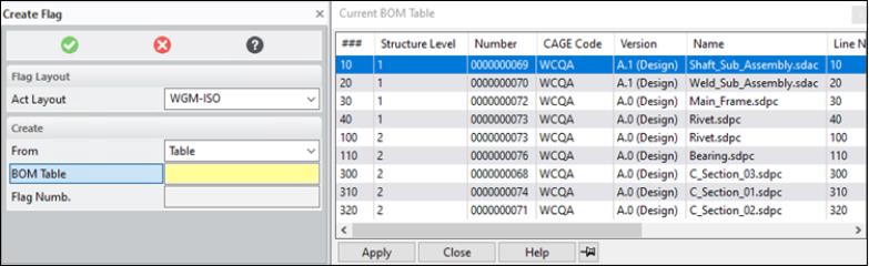
ii. In the Current BOM Table, double-click a WTPart or select a WTPart and click Apply. The corresponding geometrical elements are highlighted in the Annotation viewport.
• While assigning position flags numbers for parts that are at same position, only one is highlighted. • In multi-level BOM, there is no differentiation in highlighting between intermediate nodes and parts either using the table or the geometry. |
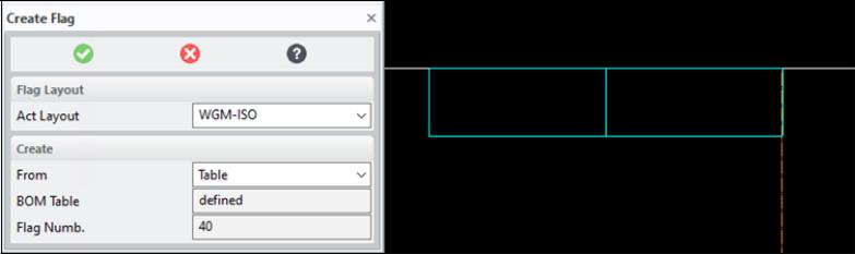
iii. Select a highlighted geometrical element, move the cursor, and click to place the position flag. The Current BOM Table reappears.
Highlighting of geometrical elements is not supported for manually included non-CAD and CAD driven WTParts. |
Here are two examples showing position flag number assignment to WTParts.
Position flag number assignment for manually added Wtparts having same WTPart Name | Position flag number assignment for WTParts with same Name |
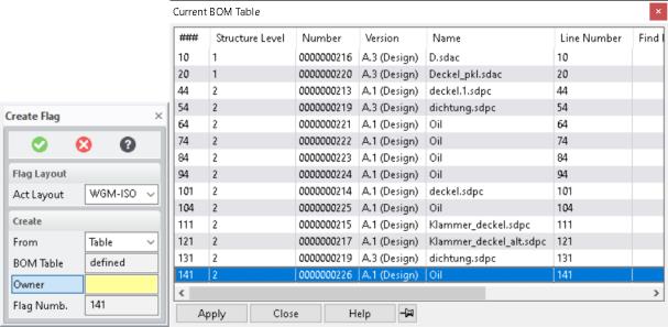 |  |
b. If you selected Table option:
i. The corresponding geometrical elements are highlighted in Green in the Annotation viewport.

ii. Select the highlighted geometrical element, move the cursor, and click to place the position flag.

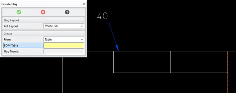
4. The Create Flag window displays the flag number of the position flag in the Flag Numb. box. The position flag is also displayed in the viewport. Zoom-in to properly view the position flag value.
5. Click  to complete the operation.
to complete the operation.After creating the position flags, if you update the Line Number value of a part in the Windchill Workgroup Manager and export the BOM report again, you must delete the existing position flags and re-assign the position flags with a new line number.
For more information on how to create and attach position flags, in the Creo Elements/Direct Modeling help, see Create position flags.
• Assigning position flag numbers for geometry under a container is not supported. • Assigning position flag numbers for geometry under finish parts (stock-finish) is not supported. |
Limitations
• If you change the WTPart number (in the Number column) in the product structure BOM, in your Windchill Workgroup Manager workspace, click > and reload the assembly.
• Position flag assignment is not supported for exporting a multi-level BOM report using the Geometry option.
• If you are exporting a single-level BOM report using Geometry option, the position flag assignment and highlighting cannot be determined while assigning to individual component views of shared or non-shared data. As a best practice, use parent view of assembly for assigning position flags instead of individual component views.
• If you are exporting a multi-level BOM report using the Table option, the individual component views of shared instance data are not properly highlighted in the drawing.
• A manually added CAD Driven WTPart does not highlight geometry because the related CAD part is not included in the CAD structure.
• A manually added non-CAD Driven WTPart (such as Oil, Packaging, etc) highlights geometry, and you can place a position flag on the geometry of a part or assembly.
• Exporting a BOM report of a WTPart having no child WTPart is not supported.
• In Creo Elements/Direct Modeling, a Selective Instance is not handled separately in BOM Export functionality.
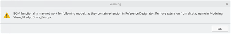
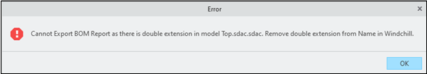
• A double extension in a top-level assembly name is not supported. An error message appears informing you that the BOM report export is prohibited.
• In Creo Elements/Direct Modeling, when you are exporting a BOM report and the display name of the child component contains extension, the geometry highlighting fails and the following error is displayed (for both Geometry and Table option).