Visualizing Advanced Features: CAD Represented Parts and Assembly Features
This topic provides details about visualizing the following advanced features:
• CAD represented parts
• Assembly features
Visualizing CAD Represented Parts and Assembly Features
When viewing a WTPart or EPMDocument structure in Creo View, or from the Visualization tab in the Product Structure Browser, the graphics for the structure are dynamically generated by merging the default representations for all objects in the structure into a single PVS file. The current navigation criteria is used to select which WTParts or EPMDocuments are selected for display.
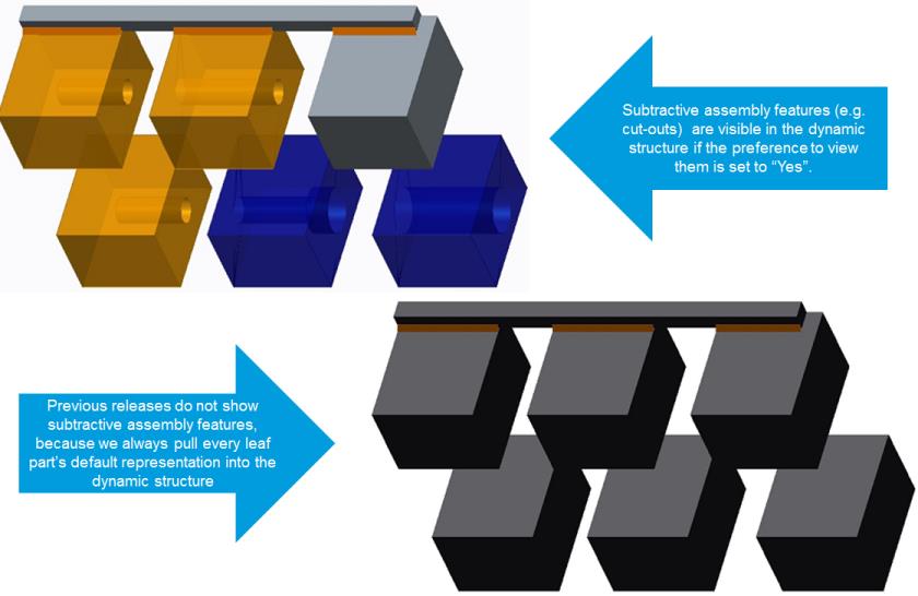
However, if a part has assembly feature cut-outs, by default, the cutouts are not visible. If a part is associated to a CAD assembly whose children do not have associated WTParts with representations, and the assembly part is published as an extended positioning assembly, the graphic for the part in the assembly cannot be visible. The following sections describe how to enable visibility of the graphic in use cases such as these.
Visualization of Assembly Features
• To enable visualization of assembly features in dynamic part structures set the user preference Assembly Features in Dynamic Part Structures to Yes.
• To enable visualization of assembly features in dynamic CAD structures, set the user preference Assembly Features in Dynamic CAD Structures to Yes.
See
Setting Visualization User Preferences for more information about setting user preferences.
Example — A WTPart Structure is associated to a CAD assembly that has assembly features and flexible components. The default representations of all assemblies at all structural levels are published as a non-positioning assembly or as extended positioning assemblies. You cannot publish an assembly that has assembly features as a positioning assembly. When dynamically viewing the part structure, the assembly features and flexible components must be displayed.
Enabling assembly features has some limitations, and can only be enabled if the limitations are understood and acceptable. The OL file containing the assembly feature is retrieved from the assembly’s representation. If there are multiple iterations/versions of the child parts, there is no way to guarantee that the OL file used to display the assembly feature is the one created for the iteration/version selected by the current navigation criteria for the assembly.
For example, if you have an assembly with two child parts with two versions each, there are four possible combinations of geometry:
• Part1 A.1, Part2 A.1
• Part1 A.2, Part2 A.1
• Part1 A.1, Part2 A.2
• Part1 A.2, Part2 A.2
When generating the part structure using the latest configuration specification, Part1 A.2 and Part2 A.2 is in the part structure. However, if Part 1 has assembly features, it uses the OL file for Part1 A.1 instead of Part1 A.2.
See
Setting Visualization User Preferences for more information about setting user preferences.
| • When viewing the structure of CAD Represented Parts in the Visualization tab, the selected objects do not always highlight the correct object in the structure because the structure is different from the viewable structure. • When viewing the CAD Represented Part in Creo View, the correct object is highlighted because Creo View displays the structure as modified by the generation of the dynamic structure. |