Best Practice for Using Multiple Part Structure Filters
Option, configuration specification, and specialized filters can be used together to display a product structure that shows only the parts that are important for the task to be performed. You can set these filters in any order; however, it is important to understand the meaning of each filter, the order you want them applied, and the affect it will have on the displayed part structure. The best practice for filtering will:
• Use option filters to display a specific product variant.
• Use a configuration specification filter to display the desired working product configuration (part versions).
• Use specialized filters to isolate a subset of parts representing a specific design context.
Suggested Filter Order
The following flow diagram and the following step-by-step use case illustrates how multiple filters are designed to work together.
The process starts with filtering a configurable part structure for the desired option choices. When choices have been made for all options the result will be a standard part structure for a specific product variant.
A configuration specification filter is then used to select the part versions for the selected optional modules. For example, a user might want to see all of the latest part versions in either the In Work or Released states. The output of the configuration specification is the matching part versions for the entire assembly configuration.
Finally, specialized spatial and attribute filters are used to reduce the assembly configuration to only those parts that are relevant to the task being performed. The task specific structure is often called a design context.
The optional part structure of an automobile is an example where multiple filters can be used. Consider the following scenario; the drivetrain option for a specific automobile model includes choices for engine and transmission. A design engineer has been assigned a task to modify selected components on the air cleaner assembly for the eight cylinder engine option. Only a portion of the parts in the air intake system will be impacted by this task. The designer uses the following part structure filters together to see only the subset of parts that are relevant to this task:
Step 1–Option Filter
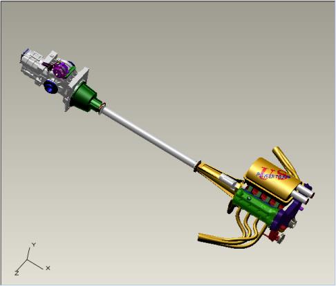
The designer opens the part structure for the configurable drivetrain assembly within the top-level automobile product structure and selects the eight cylinder engine and transmission option. The following image shows the engine and drivetrain assembly after the option filter is applied:
Step 2–Configuration Specification
The designer collaborates with others in a number of engine design projects, and it is important to see all of the latest modifications that co-workers have made along with the parts the designer will modify. The designer must also see the parts in the air intake system that are around the air cleaner and will remain unchanged so that the new design does not interfere with those existing parts. The designer sets a configuration specification filter that displays the latest part versions in the in-work state (where changes are being made), and the latest part versions in the released state (where changes are not being made).
Step 3–Specialized Filters
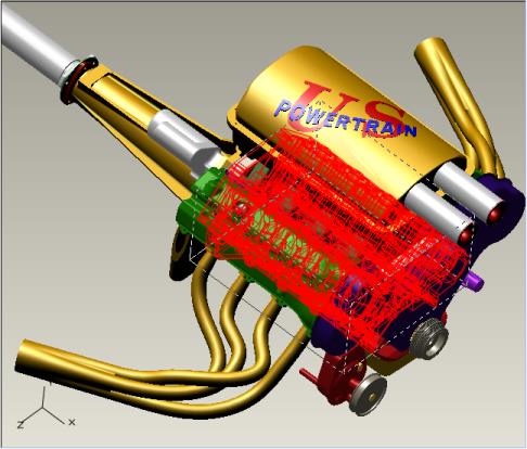
Working on the air intake system components with all other engine and transmission parts displayed complicates the designer’s task. The designer can use a spatial filter to further reduce the part structure, eliminating the transmission and drive shaft. To do this, the designer selects the engine block in the part structure and defines a proximity filter to show only the parts associated to the engine. The proximity filter returns all parts with geometry that intersects a bounding box around the engine block plus a specified proximity distance of 0.5 meters.
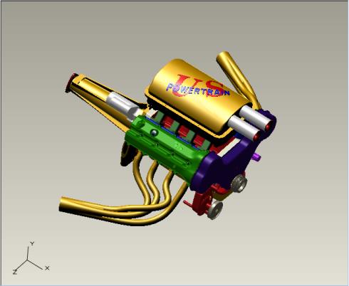
Only the engine parts are displayed after the proximity filter is applied. However, the part structure still contains many more parts than the designer needs to perform the task.
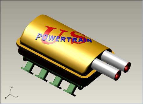
The air intake system includes the air cleaner assembly and the intake manifolds. These parts are labeled with a custom attribute called, System, with the value Air Intake. The designer adds an attribute filter to display only the parts with the System attribute set to Air Intake. The parts that are left after the attribute filter is applied are shown below:
The designer is now ready to open a CAD workspace with the displayed components. The specialized filters have reduced the engine and drivetrain module configuration to a subset of parts that are relevant to the designer’s task.
The combination of filters can be named and saved in the system for later use and shared with other design team members. For more information, see
Saving and Reusing Structure Filters.


