Visualization of Assembly Features
If an assembly contains features which modify the geometry of its children, an example being a cut-out of a child, this can cause the resulting geometry to be incorrect displayed in the dynamic visualization. If an assembly contains these types of modifications, they are typically published as a static representation or an extended positioning assembly and the correct geometry of the children will only be stored in the representation of the assembly (and not the child). This results in the dynamic structure visualization being incorrect because it loads the geometry of the child from the default representation of the child.
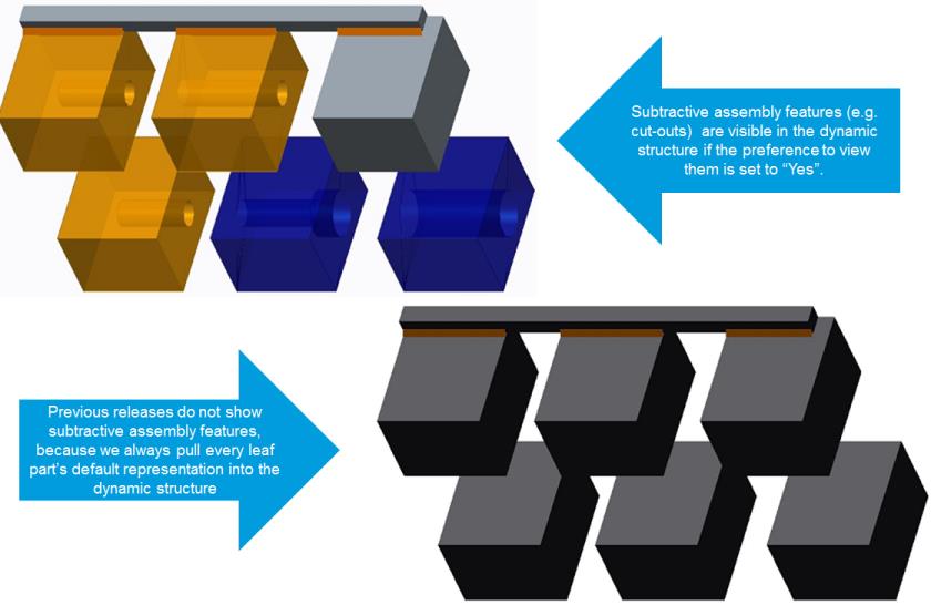
Visualization of assembly features in dynamic part structures can be enabled by setting the user preference > > to Yes. Visualization of assembly features in dynamic CAD structures can be enabled by setting the user preference > > to Yes.
Enabling this preference allows the Windchill system read the representations of assembly files and identify when an assembly feature exists. When this happens it chooses to use the resulting geometry in the assembly’s representation instead of the default representation of the child.
Handling of assembly features in dynamic visualization is limited by its ability to access the “correct” geometry based on the combination of navigation criteria applied to the structure and representations which exist in the system. The OL file containing the assembly feature is retrieved from the assembly’s representation. If there are multiple iterations/versions of the child parts, there is no way to guarantee that the OL file used to display the assembly feature is the one created for the iteration/version selected by the current navigation criteria for the assembly.
This is heavily dependent on the publishing strategy which has been developed and whether or not assemblies are being republished when it’s children are changed.
For example, if you have an assembly with two child parts with two versions each, there are four possible combinations of geometry:
• Part1 A.1, Part2 A.1
• Part1 A.2, Part2 A.1
• Part1 A.1, Part2 A.2
• Part1 A.2, Part2 A.2
When generating the part structure using the latest configuration specification, Part1 A.2 and Part2 A.2 is displayed in the part structure. However, if Part1 has assembly features, it can use the OL file for Part1 A.1 instead of Part1 A.2.