About Section Cut in MPMLink
Use the actions in the
 Section Cut
 list to view a cutout of a model along a particular direction. It allows you to view internal components of the model without the need to alter any geometry. Use the
Set Section Cut action followed by actions listed in the table:
Action | Description |
Planer/Quarter | Creates a planar cross section using a datum plane or planar surface as the reference. |
X-Axis | Creates a planar cross section with X axis of the default coordinate system as the reference. |
Y-Axis | Creates a planar cross section with Y axis of the default coordinate system as the reference. |
Z-Axis | Creates a planar cross section with Z axis of the default coordinate system as the reference. |
Using Section Cut
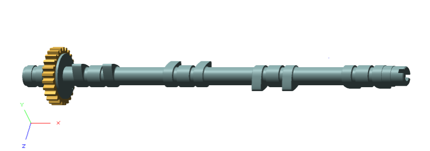
Consider the following part displayed in the Visualization tab of BOM transformer:
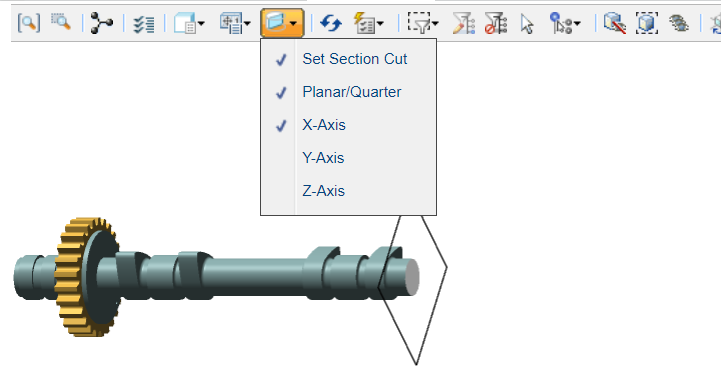
To view the part in half along the X axis, click the Set Section Cut, Planer/Quarter, and X-Axis actions:
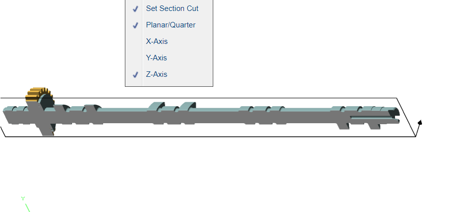
To view the part in half along the Z axis, enable the Set Section Cut, Planer/Quarter, and Z-Axis actions:
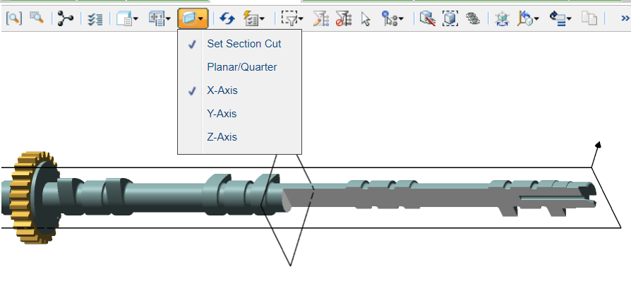
If you enable only the Set Section Cutand X-Axis actions, the part is displayed as:
Without planer option.
The
Section Cut list is available in the
Visualization tab of the following browsers in MPMLink:
• BOM Transformer
• 3D Tree Picker of Process Plan Browser
• Process Plan Browser
• Manufacturing Resource Browser
• 3D Tree Picker of Manufacturing Standard Browser
• Manufacturing Standard Browser
• 3D Tree Picker of Operation information page
• 3D Tree Picker of Advanced Manufacturing Resource Browser
For more information, refer the following topics in Creo help:
• To Create a Cross Section using View Manager
• About Part and Assembly Cross Sections topics in Creo help.