Working with Manufacturing Operations
Operations represent the steps that are executed when producing, maintaining, inspecting, or repairing parts or products. Operations are breakdown elements of a process plan which typically have a defined time associated with them and can be composed of individuals steps. Operations within a process plan are assigned a label that identifies the order in which they must be executed on the shop floor.
Each operation:
• Specifies the amount of time required to complete the operation (for example, to set-up the machine).
• Specifies the parts that are assembled in that operation.
• Specifies the resources required (machines, tooling, materials).
• Specifies the skills required.
• Has a detailed set of instructions for the shop floor operator.
• Has a single work center assigned to them.
• Can have a single illustration.
Creating Manufacturing Context for Process Plan with Part Structure Allocated to an Operation with CAD Context
Prerequisites to creating a manufacturing context:
• Representation or associated CAD file for the resource or part is available.
• CAD assembly and part structure with or without occurrences, based on your requirement
The workflow to creating a manufacturing context is as follows:
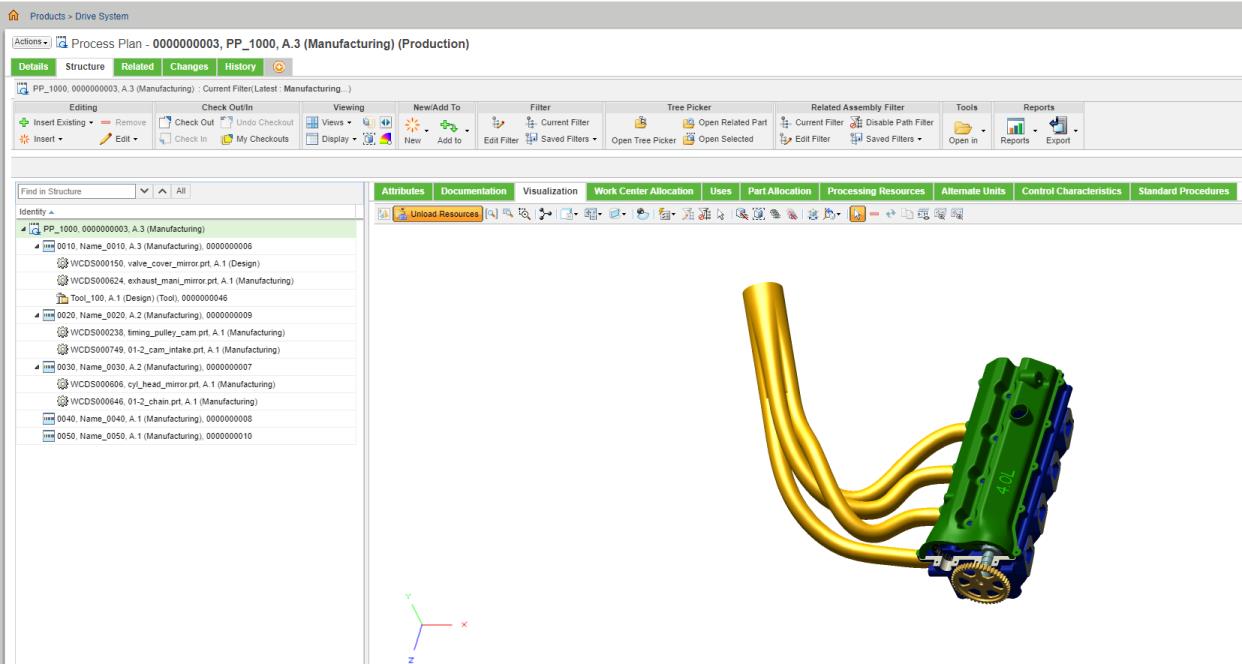
1. Create a structure with a process plan. Insert multiple operations under the process plan, then allocate parts and resources to the inserted operations.
|
|
You can also allocate assemblies from different product in a process plan.
|
2. Check in the process plan.
3. Click the Visualization tab, then click Load Resources.
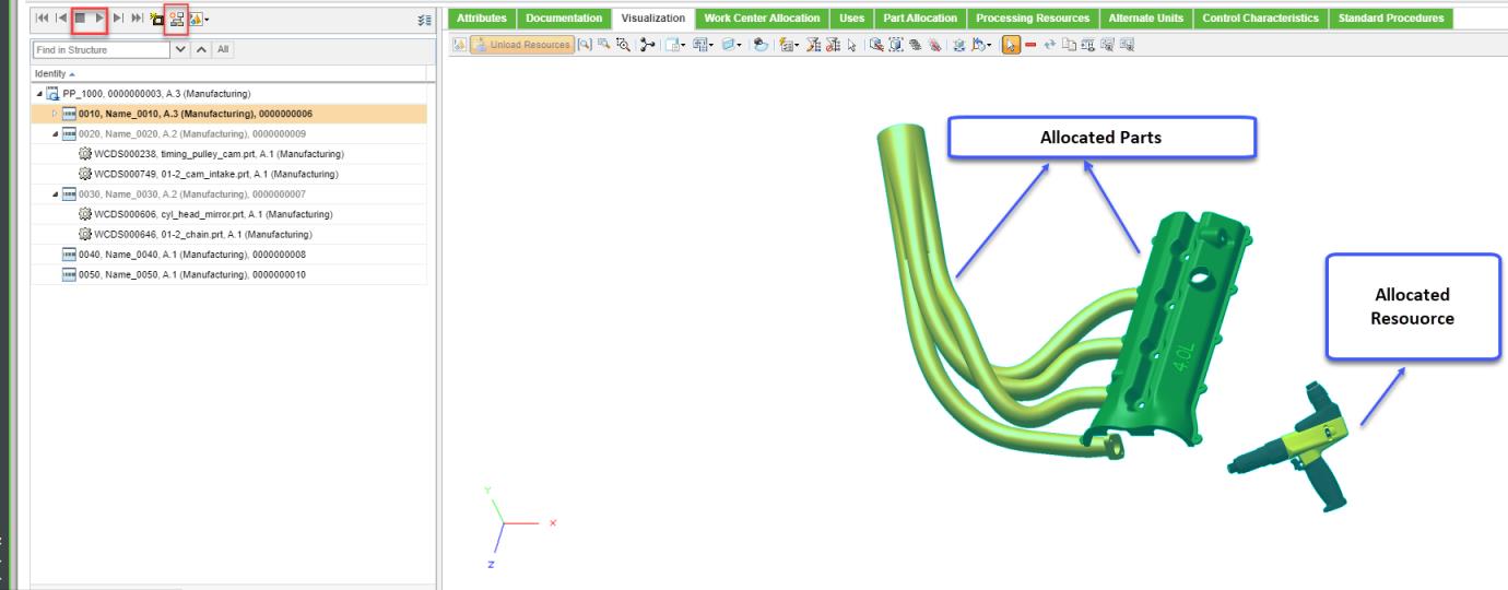
4. In the Viewing action set, click Playback Actions.
This toggles the Playback toolbar, located right above the process plan structure.
5. Click the

play icon. The selection moves to the first operation.
6. When the operation for which you want to create a manufacturing context is played, Click

in the playback toolbar.
| You can navigate through the operation using the next and previous actions in the Playback toolbar. |
7. Click

. The
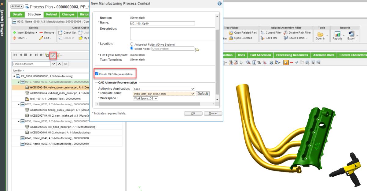
New Manufacturing Process Context dialog box opens.
8. Specify the details as necessary.
| Based on your requirement, you can select from a host of CAD options available in the CAD Alternate Representation section. |
9. Select the Create CAD Representation check box.
| The check box should be clear when you create a manufacturing context for process plan with part structure allocated to an operation with CAD context. |
10. Click OK. The manufacturing context is created. A banner appears confirming that the manufacturing context is created.
You can create a separate manufacturing context for every assembly added to a process plan.
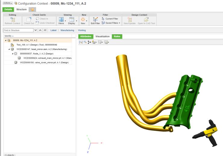
From the folder contents page or from the banner message, you can open the newly created manufacturing context and view the content and the following information:
• Resource allocated to the operation that is currently played.
• Parts allocated to the current operation and all the parts allocated to previous operations.
The following considerations apply for the newly created manufacturing context:
• In a Manufacturing Context structure, the part allocated to an operation is assembled under the allocated root assembly.
• The allocated resource is assembled under the context and not under the part structure.
• The part structure and resource are allocated to a plant that is generated with same identity as Manufacturing Context. The format for the name of the generated plant is as follows: MC_<Number>.
• Plant information is updated as Attribute value named Context Part.
• If the CAD representation for resource is repositioned using Creo or Creo View, the manufacturing context created for the operation displays the updated position. The updated position is retained in the visualization pane.


 play icon. The selection moves to the first operation.
 in the playback toolbar.
 . The New Manufacturing Process Context dialog box opens.
