Deployment Scenarios
This section provides someWindchill ESI deployment scenarios as high-level examples of physical network and computing requirements for simple, mid-sized, and complex environments.
|
|
These scenarios are not intended to be prescriptive, but rather to provide a framework from which skilled systems integrators can tailor aWindchill ESI deployment for a particular business’ needs. Certain components, such as network routers and data storage systems, are simplified or omitted.
|
Simple Environments
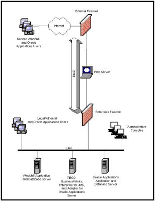
If you are a smaller organization wishing to deploy all EAI components on a single physical server to minimize cost, the following figure illustrates a simpleWindchill ESI deployment that you can use as an example.
In this sample scenario,Windchill PDMLink product designers are co-located with manufacturing users. The Windchill ESI-EAI software components are consolidated on a single physical server. If required, the Windchill and TIBCO servers can also be combined onto one physical server. This scenario illustrates the following best practices to help maximize performance:
• If possible, deploy the TIBCO Adapter for Oracle Applications on the same LAN as the target Oracle Applications system.
In this scenario,Windchill PDMLink and Windchill ESI users and administrators work on a common LAN with direct access to the back-end systems. External users ofWindchill ESI and Windchill ESI systems enter the enterprise through a web server in a secure demilitarized zone (DMZ).
Windchill ESI in a Simple Environment
Mid-Size Environments
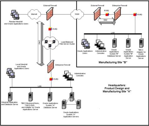
If you are a mid-sized company with scalability requirements and are seeking a reasonable balance between factors such as cost, performance, and reliability, you can use, as an example, the scenario presented in the following figure.
The preceding figure illustrates a two-site scenario in which a more complex production system is housed at the company headquarters (Site A) with product designers and manufacturing users. Another site, (Site B) is separated from headquarters by a Wide-Area Network (WAN) link and requires using Rendezvous Routing Daemons (RVRDs) to pass Rendezvous messages across a WAN and firewalls. Each target system has its own TIBCO Adapter for deployment on the same LAN.
Complex Environments
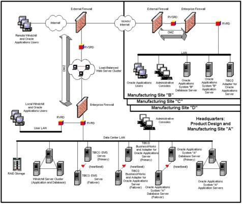
If you are a large company, geographically dispersed with complex or special business requirements such as traversing WANs and firewalls, with multiple manufacturing sites, large data volumes, and high availability and high security needs, you could use the exampleWindchill ESI deployment illustrated in the following figure.
Windchill ESI in a Complex Environment
The preceding figure illustrates a multiple-site scenario. Site A represents the company headquarters, containing product design and manufacturing facilities. Sites B, C, and D represent remote manufacturing sites, either within the corporation (separated by private WAN links), or external to the corporation (such as third-party, contract manufacturers separated through the internet). Site A makes extensive use of clustering and redundancy in the physical servers to facilitate high-availability (that is, fail-over and fail-back capabilities). TIBCO BusinessWorks process engines are deployed on the both the primary and failover servers to provide better performance for concurrent product data publishing operations between Windchill and Oracle. For security reasons, end-users use a separate LAN rather than the back-end systems and communications over the Internet which are brokered by secure routing daemons (RVSRD).