Visualizing Dynamic Structures
This topic contains the following sections:
• Visualization of Assembly Features
• Visualization of Creo Parametric Flexible Assemblies
• Visualization of CAD Represented Parts
• Visualization of Image-Associated and Contributing Image-Associated Parts in Dynamic Part Structure
• Customization of WTPart Structure
• Additional Administrative Preferences Affecting Dynamic Visualization
• Identifying Parts as CAD Represented Parts
• Example: CAD Represented Part XML Configuration
When viewing a WTPart or EPMDocument structure in Creo View, or from the Visualization tab in the Product Structure Browser, the graphics for the structure are dynamically generated by merging the default representations for objects in the structure (Part or CAD) into a single PVS file. The current navigation criteria is used to select which WTParts or EPMDocuments are selected for display.
When visualizing these structures there can be several situations where the expected visualization that the user might like to see is not held on the default representation of the parts in the structure. This section will walk through how to handle these different types of situations and considerations when modifying the behavior of the dynamic visualization.
Visualization of Assembly Features
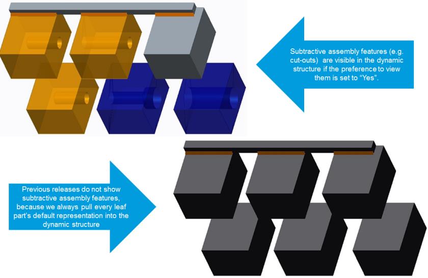
If an assembly contains features which modify the geometry of its children, an example being a cut-out of a child, this can cause the resulting geometry to be incorrect displayed in the dynamic visualization. If an assembly contains these types of modifications, they are typically published as a static representation or an extended positioning assembly and the correct geometry of the children will only be stored in the representation of the assembly (and not the child). This results in the dynamic structure visualization being incorrect because it loads the geometry of the child from the default representation of the child.
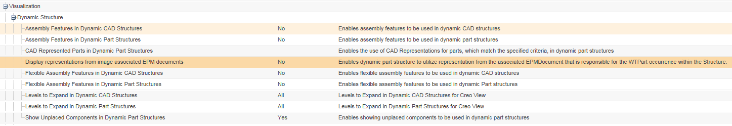
Visualization of assembly features in dynamic part structures can be enabled by setting the user preference > > to Yes. Visualization of assembly features in dynamic CAD structures can be enabled by setting the user preference > > to Yes.
Enabling this preference allows the Windchill system read the representations of assembly files and identify when an assembly feature exists. When this happens it chooses to use the resulting geometry in the assembly’s representation instead of the default representation of the child.
Handling of assembly features in dynamic visualization is limited by its ability to access the “correct” geometry based on the combination of navigation criteria applied to the structure and representations which exist in the system. The OL file containing the assembly feature is retrieved from the assembly’s representation. If there are multiple iterations/versions of the child parts, there is no way to guarantee that the OL file used to display the assembly feature is the one created for the iteration/version selected by the current navigation criteria for the assembly.
This is heavily dependent on the publishing strategy which has been developed and whether or not assemblies are being republished when it’s children are changed.
For example, if you have an assembly with two child parts with two versions each, there are four possible combinations of geometry:
• Part1 A.1, Part2 A.1
• Part1 A.2, Part2 A.1
• Part1 A.1, Part2 A.2
• Part1 A.2, Part2 A.2
When generating the part structure using the latest configuration specification, Part1 A.2 and Part2 A.2 is displayed in the part structure. However, if Part1 has assembly features, it can use the OL file for Part1 A.1 instead of Part1 A.2.
Visualization of Creo Parametric Flexible Assemblies
Flexible assemblies provide the ability for a parent assembly to override the positioning information of one of its children assembly’s components. This means that in the case of dynamic visualization, the location of the component is loaded from the parent assembly’s representation. This overrides the position present in the lower child assembly.
Flexible assemblies are visible in their alternate location in dynamic CAD or Part structures as dictated by their parent assemblies when opening the dynamic CAD or Part structure in Creo View and its user preference is set to Yes.
• > >
• > >
When a dynamic structure with flexible features and assembly features is used, the geometry from the parent assembly is used for the assembly features, and the transforms (locations) from the parent assembly are used for the flexible features.
| Flexible assemblies are supported by Creo View Adapter for Creo Parametric 5.0 or later only. |
Visualization of CAD Represented Parts
When a dynamic part structure is displayed, the graphics are composed of the merged representations of parts in the structure. For certain WTParts, the child part structure is either not present, or is incomplete and the children do not have graphics associated to them. Supplier parts are an example of this. With supplier parts, there is a single WTPart in the structure which represents the complete supplier assembly. In these cases, the 3D graphic is not complete. WTPart structures that are missing the child part structure are called CAD Represented Parts.
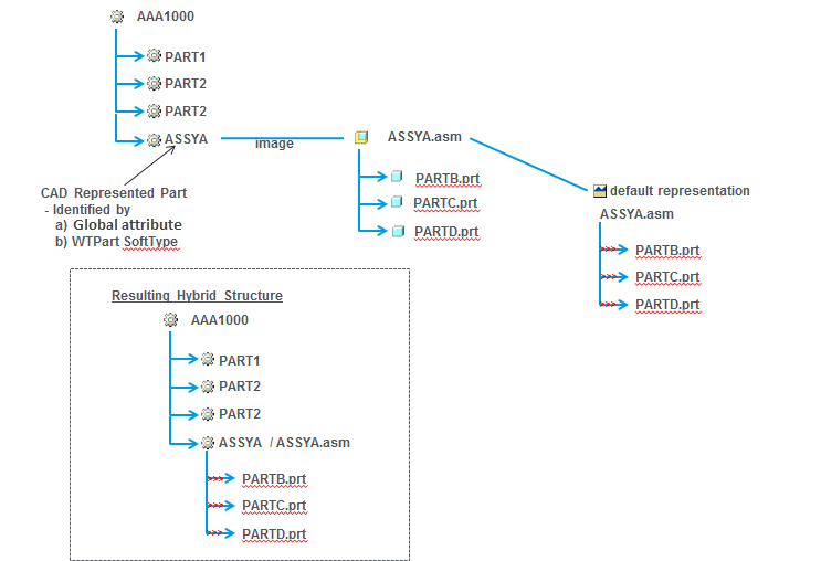
It is possible to configure Windchill to display the 3D graphic for CAD Represented Parts. The whole representation of CAD Represented Parts is used to display the 3D graphic. The representation used to display the graphic is the default representation of the part. If the default representation is missing, it uses the default representation on an image associated EPMDocument, and the complete representation, including all children, is merged. Any child WTParts of the CAD Represented Part in the WTPart structure are removed from the visualization structure.
In the example below, WTPart “ASSYA” has an image association to a CAD Assembly that has three children. The CAD Assembly has a published representation. When this part is identified as a CAD Represented Part, the resulting visualization structure includes the children of the CAD Assembly.
Visualization of Image-Associated and Contributing Image-Associated Parts in Dynamic Part Structure
The dynamic part structure of a WTPart displays the default representation of an owner-associated EPMDocument. However, if the WTPart is associated with one or more EPMDocuments and the representation used in the CAD structure is an image-associated or contributing image-associated EPMDocument, then the dynamic part structure may not display correctly.
For such image-associated or contributing image-associated EPMDocument representations to display correctly in the dynamic part structure for Creo View or Visualization tab, enable the Display representations from image associated EPM documents preference by setting it to Yes as mentioned below.
> > to Yes
After the preference is enabled, the system can read the information of the occurrence link in the part structure and identify the image-associated or contributing image-associated EPMDocuments used in the structure. This information is used to display the correct representations in Creo View or in the Visualization tab of the Product Structure Browser.
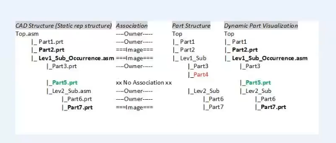
If a part structure is built with a child from an image-associated or contributing image-associated EPMDocument assembly with children, then for this occurrence in the part structure, the image-associated or contributing image-associated representation is used to determine the children and their position for that node in the structure. The children are then compared with the part structure's children to identify matching pairs and continue loading from the part structure. If there are mismatching children, the geometry and structure of the image-associated or contributing image-associated representation is used instead of the part structure. As a result, the geometry is formed from the EPMDocument but retains the configuration specification and cross-selection capabilities of the part structure.
In the following example, though the part structure assembly contains Part4, but since it is not included in the CAD structure, it is not displayed in the dynamic part structure.
Customization of WTPart Structure
It is possible to modify the way WTPart dynamic structures are generated by providing a custom hook to exclude parts, use representations other than the default representation of the part, or to include the entire representation for an assembly instead of merging the representations associated to its children. For more information, see the “Modifying the Default Behavior of Dynamic Part Generation” section of the Windchill Customization Guide, or by examining <Windchill>\prog_examples\wvs\com\ptc\wvs\PartStructureFilter.java.
Additional Administrative Preferences Affecting Dynamic Visualization
The following WVS properties are used to control the visualization of Assembly Features:
WVS Property | Description |
edrload.dynamicpartstructure.excludeassemblyrepresentations edrload.dynamiccadstructure.excludeassemblyrepresentations | Default Value: True Synopsis: Specifies whether to exclude representations with additive assembly features. These properties are used to improve performance when generating the dynamic structure. They do not impact the actual end result; that is, the dynamic structure is the same regardless of what the property is set to. Description: These properties specify whether to exclude representations of assembly parts or CAD Documents that have additive assembly features (such as welds and pipes) from the dynamic CAD part structure. The property defaults to True if it is absent. | This property’s performance gain is realized for representations published with a Creo View adapter that injects data into the PVS file to indicate whether there are assembly features. Currently, the only adapter that supports this is the Creo Parametric adapter, beginning at Creo View 3.0 M020. |
|
edrload.dynamicpartstructure.versionmismatch | Default Value: WTPart Synopsis: Specifies what version mismatch warnings are displayed when opening Creo View. Description: This property is used to configure how version mismatch warning messages are displayed when users view Dynamic Part Structures with Assembly Features processing enabled. Specifically, a warning message is displayed when there is a version mismatch between the CAD documents. There are four possible values for this property: • WTPart — Only Part version mismatches are displayed in the warning message. • EPMDocument — Only EPMDocument mismatches are displayed in the warning message. • EPMDocumentRevertToWTPart — EPMDocument mismatches are displayed in the warning message. If it is not possible to detect if there is an EPMDocument mismatch, it checks if the WTPart is a mismatch. • Both — Both WTPart mismatches and EPMDocument mismatches are displayed in the warning message. The property defaults to WTPart if not specified, or if it is not set to one of the values specified above. |
publish.cadconvert.PROE.getalldependentsforextposassy | Default: False Synopsis: Application Type to Java class lookup. Description: Valid for type PROE when publishing as an extended positioning assembly. If set to True, the representation retrieves dependent files from components of all assembly levels in the assembly structure. If set to false , only the first-level components in the assembly structure is retrieved. | Setting this property to True has an impact on performance. Set his property to True for customers using a modeling practice that creates assembly features for non-direct children at the top-level assembly. |
|
edrload.dynamiccadstructure.donotreadpvs edrload.dynamicpartstructure.donotreadpvs | Default Value: True Synopsis: Specifies whether to read the PVS file of representations when viewing dynamic CAD structures or PART structures in Creo View or in the Visualization tab. Description: The dynamic structure of a representation that has a pvsfile with a single component is generated on the server without reading the pvsfile from the vault. To allow the dynamic structure generation to recognize if this representation is suitable for not reading the pvsfile, representation is marked with a new OL file name flag. If set to True, the performance while loading Dynamic CAD and Part structures in Creo View and in Visualization tab improves. If set to false, WVS read the PVS file for each component. |
Identifying Parts as CAD Represented Parts
Configuring groups for identifying CAD Represented Parts — An XML file is used to control the definition of what is identified as a CAD Represented Part. The XML file can be configured to have multiple groups to represent CAD Represented Parts. Each group can consist of multiple global attributes and/or WTPart Soft Types. A WVS preference, available in the Site and Organizations contexts at > > , configures the location and name of the xml file used to configure parts identified as CAD Represented Parts. The location can be specified relative to the <Windchill> directory or can be absolute. For detailed information on how to create a configuration file for identifying CAD Represented Parts, including the ability to localize the name and description, refer to the CADRepresentedPartConfiguration.xml file located at <Windchill>\codebase\com\ptc\wvs\server\xml\ .
| When the XML file is updated, it must be reloaded into Windchill. The administrator can update the preference and click OK to upload the changes; otherwise, the file will be updated the next time the method server starts. |
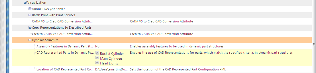
User Preference for selecting groups used to identify CAD Represented Parts — Users can select which groups they want to use for identifying parts as CAD Represented Parts by setting the > > user preference. In the example below, Bucket Cylinder, Main Cylinders, and Head Lights are all selected for identifying parts as CAD Represented Parts.
User Preference for determining whether to show unplaced components to be used in dynamic part structures — Users can decide whether to display unplaced components to be used in a dynamic part structure by setting the > > user preference. For example, when this preference is set to Yes, unplaced components are displayed when opening the dynamic part structure in Creo View.
| When viewing the structure of CAD Represented Parts in the Visualization tab, the selected object does not always highlight the correct object in the structure, because the structure is different from the viewable structure. When viewing the CAD Represented Part in Creo View, the correct object is highlighted because Creo View is displaying the structure as modified by the generation of the dynamic structure. |
Example: CAD Represented Part XML Configuration
An example XML file showing control of CAD Represented Part Filtering is provided below.
Group 1 defines an IBA-named "cad-represented-part" in which its value starts with "crp"
<!-- ####################################################### --> <!-- This configuration file is used by dynamic part structure visualization to control the CAD Represented Part Filtering. --> <!-- --> <!-- ####################################################### --> <!-- # The following XML elements and attributes are used to control CAD Represented Part Filtering # --> <!-- # defined by the following XML schema CADRepresentedPartConfiguration.xsd # --> <!-- ####################################################### --> <!-- --> <!-- Element: "cad-represented-parts" = Declaration element for all control options pertaining to CAD Represented Part Filtering. --> <!-- Element: "group" = defines a set of CAD Represented filters displayed on the UI --> <!-- Attribute: "id" = String value representing a unique id for the "group" element. --> <!-- Attribute: "name" = If attribute "resource_name" is defined the value is used to access the entry in the resource --> <!-- bundle for the name of the "group" else if "resource_name" is not present the value will --> <!-- be displayed as is on the UI for the name of the "group" element. --> <!-- Attribute: "description" {optional} = If attribute "resource_name" is defined the value will be used to access the entry in the --> <!-- resource bundle for the description of the "group" else if "resource_name" is not defined --> <!-- the value will be displayed as is on the UI for the description of the "group" element. --> <!-- Attribute: "resource_name" {optional} = Resource class to use to pull the "name" and "description" attribute values from. --> <!-- If this is defined for a "group" element the attributes "name" and "description" --> <!-- on the "group" element will be used as the keys to the entries in the resource file. --> <!-- Attribute: "default" {optional} = Sets the default value for the preference "group" to checked (enabled) or --> <!-- unchecked (disabled), if not defined the default will be "disabled" --> <!-- Element: "iba" = Defines a single part attribute to indicate the part as a "CAD Represented Part". --> <!-- Element: "name" = An attribute name that exists on a part in which its value can be used to determine if a part is --> <!-- a "CAD Represented Part". NOTE: The IBA types supported for this feature are String and boolean --> <!-- Element: "regex" = A Java regular expression used to determine if the attribute value equates to a "CAD Represented Part" --> <!-- Element: "object-type" = String name of a Windchill defined WTPart or soft type of WTPart. --> <!-- --> <!-- ############# --> <!-- # Example 1 # --> <!-- ############# --> <!-- Defines Two cad-represented-parts: --> <!-- Group 1 defines an IBA named "cad-represented-part" in which its value starts with "crp" --> <!-- and will be considered a CAD Represented Part. The group is enabled. --> <!-- --> <!-- Group "name" will be displayed as the string literal: "Name of the group displayed on the preference UI" --> <!-- Group "description" will be displayed as the string literal: "Description of group displayed on preference UI" --> <!-- --> <!-- Group 2 defines an IBA value of "cad-represented-part2" --> <!-- in which if its value is true will be considered a CAD Represented Part, The group is disabled. --> <!-- NOTE: Must use true or false for the regex value for boolean attributes. --> <!-- --> <!-- Group "name" will be displayed as the string literal: "Name of the group displayed on the preference UI" --> <!-- Group "description" will be displayed as the string literal: "Description of group displayed on preference UI" --> <!-- --> <!-- <cad-represented-parts> --> <!-- <group id="1" name="Name of the group displayed on the preference UI" --> <!-- description="Description of group displayed on preference UI" default="enabled"> --> <!-- <iba> --> <!-- <name>cad-represented-part</name> --> <!-- <regex>crp.*</regex> --> <!-- </iba> --> <!-- </group> --> <!-- <group id="2" name="Name of the group displayed on the preference UI" --> <!-- description="Description of group displayed on preference UI" default="disabled"> --> <!-- <iba> --> <!-- <name>cad-represented-part2</name> --> <!-- <regex>true</regex> --> <!-- </iba> --> <!-- </group> --> <!-- </cad-represented-parts> --> <!-- --> <!-- ############# --> <!-- # Example 2 # --> <!-- ############# --> <!-- Defines a "cad-represented-parts" with one entry which --> <!-- defines the entry for "object-type" to have a value of "org.rnd.ECADSoftType" which is a Windchill softtype, The --> <!-- group is disabled. --> <!-- --> <!-- Group "name" will be displayed as the string literal: "Name of the group displayed on the preference UI" --> <!-- Group "description" will be displayed as the string literal: "Description of group displayed on preference UI" --> <!-- --> <!-- <cad-represented-parts> --> <!-- <group id="1" name="Name of the group displayed on the preference UI" --> <!-- description="Description of group displayed on preference UI" default="disabled"> --> <!-- <object-type>org.rnd.ECADSoftType</object-type> --> <!-- </group> --> <!-- </cad-represented-parts> --> <!-- --> <!-- ############# --> <!-- # Example 3 # --> <!-- ############# --> <!-- Defines a cad-represented-parts with three entries and is enabled: --> <!-- First entry defining an IBA value "cad-represented-part" in which if its value is true --> <!-- will be considered a CAD Represented Part. --> <!-- NOTE: Must use true or false for the regex value for boolean attributes. --> <!-- Second entry defining a soft type value of "org.rnd.ECADSoftType1" --> <!-- Third entry defining a soft type value of "org.rnd.ECADSoftType2" --> <!-- --> <!-- Group name is defined by the resource class and key pairs: --> <!-- resource class = "com.ptc.wvs.resource" defined by the attribute "resource_name" on element "group" --> <!-- resource key = "name_key" defined by the attribute "name" on element "group" --> <!-- Group description is defined by the resource class and key pairs: --> <!-- resource class = "com.ptc.wvs.resource" defined by the attribute "resource_name" on element "group" --> <!-- resource key = "description_key_key" defined by the attribute "name" on element "group" --> <!-- --> <!-- <cad-represented-parts> --> <!-- <group id="1" name="name_key" --> <!-- description="description_key" resource_name="com.ptc.resource" default="enabled"> --> <!-- <iba> --> <!-- <name>cad-represented-part</name> --> <!-- <regex>true</regex> --> <!-- </iba> --> <!-- <object-type>org.rnd.ECADSoftType1</object-type> --> <!-- <object-type>org.rnd.ECADSoftType2</object-type> --> <!-- </group> --> <!-- </cad-represented-parts> --> <!-- ####################################################### -->
-<cad-represented-parts>
-<group default="enabled" description="Defines an IBA named CRP
where all objects that match the Java regex 'crp.*'
will be treated as a cad represented part."
name="CAD Represented Part" id="1">
-<iba>
<name>CRP</name>
<regex>crp.*</regex>
</iba>
</group>
</cad-represented-parts>