Comparing Part Structure to CAD Document Structure
You use the Compare Part to CAD Document window to make a side-by-side comparison of a Windchill part structure and its associated CAD structure. The window uses status glyphs (symbols), in two columns to indicate child differences and build status. The Child Difference column shows a glyph if any child of this object has a difference. This helps you understand which subassemblies to expand to see the differences. Where differences exist, glyphs in the Build Status column indicate the intent to build or not build a part into the part structure during the next triggered build of the part structure from the CAD structure.
You open the Compare Part to CAD Document window from the information page of a Windchill part by selecting one of the following options:
• Compare to CAD Structure from the Structure tab tool bar.
• > from the Actions menu.
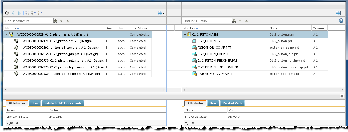
A Compare Part to CAD Document window displaying sample data is shown in the following figure.
Procedure
To compare a Windchill part structure to a CAD document structure:
1. Open the Compare Part to CAD Document window from the information page of the Windchill part whose structure you want to compare.
The Part to CAD Document Browser - Initial Values Selection window opens, displaying the identifying attributes of the part (left side), and the associated CAD Document (right side) whose structures were selected for comparison.
| • The initial values for the part structure are derived from the information page you have been viewing. The CAD information updates to describe the related Owner CAD document associated with the currently selected part. • Because any eventual modifications to the CAD document structure must be performed in the context of a workspace, you are asked to accept the current workspace or select an alternate in the Edit in Workspace field on the right side. • Comparison of part and CAD structures is limited to the comparison of the latest configuration. |
2. If the named structures are acceptable for the comparison, click OK to continue.
The Compare Part to CAD Document window displays both structures side-by-side.
3. Compare the two structures displayed in the window and check for the following conditions:
◦ Structure synchronization — A one-to-one correspondence between all of the parts in the part structure and their associated CAD documents in the current CAD structure. Look for an equal number of mutually associated objects in each structure tree.
◦ Structure differences — When the compared structures differ, those differences are highlighted by several flags. For example, when one structure has a child that currently has no associated complement in the other structure, that child appears in red text and a corresponding blank row appears in the other structure.
| In the status columns between the two structure panels, symbols are used to indicate differences. For symbol descriptions, see the following table. |
| In the case where a child object in one structure does have an associated complement, but that complementary object is not a currently participating in the complementary structure, the non-participating object appears in grayed-out text. |
Comparison Indicators
The two columns between the structures can contain symbols to indicate differences between the structures. The
Child Difference column displays the
 Child Modified
 indicator if there is a difference between the part and CAD document structures among any of the component objects of the row where the indicator is displayed. In the
Build Status column, the symbols in the following table indicate the intention to resolve differences, or leave differences unresolved.
Symbol | Meaning | Description |
| Child Modified | Indicates that a difference exists among one or more children of this component. |
| Existing Part Not In Structure | The CAD Structure uses this CAD Document and it is associated to a part; but the part is not used in the part structure. The Build Part Structure action will insert the existing part into the part Structure. (The part is listed, but in grayed-out text). |
| Not Needed in Part Structure | The CAD structure does not have a uses link that matches the part occurrence. The Build Part Structure action will remove this part uses occurrence. |
| Update Required | Information on the part occurrence is different than the related CAD document Uses link. Any mismatch in reference designator, component name, or location of the components will be synchronized. |
| Image Association | The part has ONLY image associations to CAD documents. Only CAD documents with Owner association are shown in the structure. Use the Related CAD Documents tab below to see the CAD documents related to the part with other association types. |
| No Related Part | This CAD document was inserted into the CAD document structure; but there is no related part to insert into the part structure. To resolve this difference, you must first create or associate a part to this CAD document, and then use the build part structure action. |
| Never Built | The CAD document and the part have never been built after their association. |
| Not Built | The CAD document and the part were built at least once after the association, and then either the CAD document or the part were iterated after the build. |
| Tool tips appear when you hover your mouse over the symbols to provide more information about a specific difference or status. A combination status may appear when it applies to both a link and an object. For example, Update Required and Not Built. |
Window Actions
In addition to basic structure to structure comparison, the Compare Part to CAD Document window allows you to edit structure and drive changes from one structure to another. To enable this ability, the following actions are provided:
Action | Description |
 Refresh Compare Refresh Compare | Refreshes the compare window to the initial state. If, however, the selected part has been updated, the latest structure and its associated CAD structure are populated in the window. |
 Previous Difference | Selects and highlights the row containing the previous (higher in structure) difference in the structure. |
 Next Difference | Selects and highlights the row containing the next (lower in structure) difference in the structure. |
 Set for Build Set for Build | |
 Build one level CAD structure Build one level CAD structure | Initiates an immediate build of the CAD document structure of the selected rows only. |
 Build multi-level CAD structure Build multi-level CAD structure | Initiates an immediate build of the CAD document structure of the selected rows and all children of the selected row objects. |
Information Tabs
The Compare Part to CAD Document window features tabs that can display information about the specific row selected in the structure tree above. Just as selecting an object in one structure automatically selects the associated object in the other structure (if any), the information displayed in the tabs updates to describe the selected objects on both sides of the structure comparison.
Attributes Tab
Selecting the Attributes tab displays only the attributes and values for the structure children (if any) that contribute to the build or life cycle status.
Uses Tab
Selecting the Uses tab displays the immediate children of the object selected in the main portion of the comparison window. Changing the object row selected in the main portion of the window refreshes the contents of the Uses tab table to display the direct children used by the objects in the newly selected row.
The
Uses tab on the part structure side includes the
Set for Build action to allow you to specify a build status for a selected object. For more information, see
Using the Set for Build Window.
Related Parts/Related CAD Documents Tab
Selecting the Related Parts tab (on the CAD structure side) or the Related CAD Documents tab (on the part structure side) displays the objects associated to the selected row in the structure above. For example, you can see the drawings related to parts, or the other CAD documents with Image associations (non-native CAD file copies, different states of a flexible component, and so on).
Related Topics