AutoCAD Blocks
You can create
Windchill part structures from
AutoCAD blocks.
Windchill provides an infrastructure for creating BOMs from
AutoCAD drawings. The two preferences associated with the blocks feature are
AutoCAD Blocks Configuration File Location and
Enable generation of a WTParts Structure from AutoCAD DWG files. For more information on these preferences refer to the
Workgroup Manager Client Category section located in the Client and Server Preferences chapter. When enabled, you can specify which blocks are exposed to
Windchill. Upon checkin, the drawing and the associated blocks are represented as parts with the block information included. These blocks will be used in the creation of BOMs.
The next steps describe the process for creating a BOM from AutoCAD blocks.
1. Enable the blocks feature in the Preference Management utility.
2. Save the drawing to the workspace.
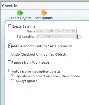
3. Check in the drawing to the workspace using the custom checkin option and selecting the Auto Associate Parts to CAD Documents option.
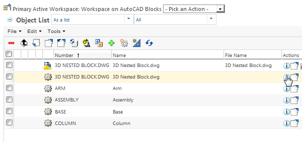
4. When the check in is complete, the drawing and the associated blocks appear in the parts list.
These parts can be used in the creation of a BOM.
The main drawing name is 3D NESTED BLOCKS.DWG. The Nested Block structure available in the drawing is:
Assembly
◦ |_ARM
◦ |_BASE
◦ |_COLUMN
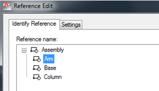
From AutoCAD navigate to > , this shows the structure:
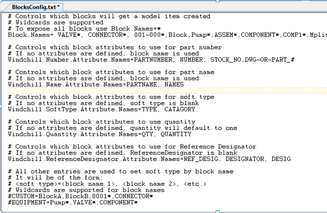
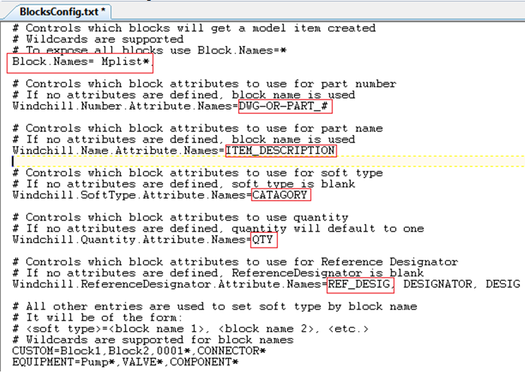
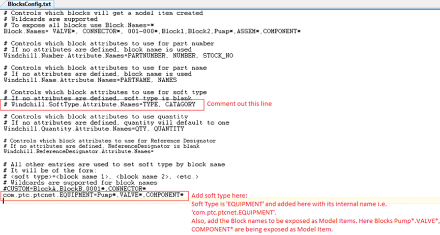
The BlocksConfig.txt file settings appears as follows:
| The block structure will be created when the following conditions are met. • The configuration settings are defined in the BlocksConfig.txt file. • Enable generation of WTParts Structure from AutoCAD DWG files preference is set to Blocks. • Checkin is performed from AutoCAD with the Auto-Associate option selected. • The reference designator value is only populated when its attribute is defined in the BlocksConfig.txt file and in the AutoCAD drawing with the model item information available in Windchill. If the reference designator attribute is not defined, it will have no value and be blank. |
Additional Windchill Preferences affecting the AutoCAD Model Item Support
Set the ‘Create Associate New Part’ preference to ‘All’ for AutoCAD application to always generate associated WTPart for AutoCAD block Model Item. Model Item type for AutoCAD is ‘COMPONENT’. Set the ‘Disallow Structure Model Item Types’ preference to ‘COMPONENT’ for AutoCAD application, if association is to be created as ‘Image’ link.
| • In case your requirement is to manage nested WTPart structure from nested block attributes, then setting this preference is not recommended, as ‘Image’ association does not drive the structure below it in the BOM report. • Set the ‘Build Image association by Default’ preference to ‘No’, if preference ‘Disallow Structure Model Item Types’ is set to ‘COMPONENT’ for AutoCAD. |
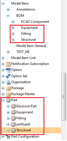
Creating an AutoCAD Block Part Structure Using Attributes
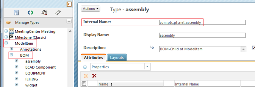
1. Create subtypes in > > as shown below.
| You can also create part subtypes, if needed and map them to the Model Item subtype. If you have not created and mapped the part subtype to Model Item subtype, the Model Item created for the block will have a default part type. |
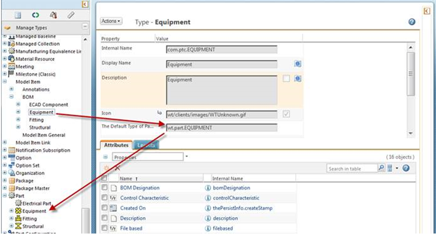
2. Map the part subtype to the Model Item subtype (if part subtypes are created) by specifying the part subtype using the field The Default type of Part to Create.
3. Add the attribute name in the BlocksConfig.txt file for Windchill.SoftType.Attribute.Names this is used to designate the subtype created while adding attributes in the Attribute Definition window in AutoCAD for the specific block.
While defining attributes for the block, add an attribute with the attribute name defined in the BlocksConfig.txt file for the block that needs to be exposed as Model Item. See the image below as a reference to the information added.
4. The AutoCAD block has attributes defined in the Drawing file, as shown in the next figure.
| • Uniqueness of the block item is controlled with Reference Designator attribute value, if its value is defined; that is, With attribute defined for property ‘Windchill.ReferenceDesignator.Attribute.Names’ in BlockConfig.txt. So when the block is placed at multiple location on drawing with different identification value for Reference Designator attribute, BOM will generate single usage link based on Number attribute and with multiple occurrence links as per the number of instances of the same block or according to the “Windchill.Quantity.Attribute.Names” attribute value defined in blocks. Reference designator value will be propagated to usage/occurrence link according to each block values. When multiple block instances with same Number attribute contains duplicate reference designator values, then check-in will fail as uniqueness is controlled with property ‘Windchill.ReferenceDesignator.Attribute.Names’. • When ‘Windchill.ReferenceDesignator.Attribute.Names’ attribute is not defined in the block and same block with Number attribute is placed at multiple location on drawing, BOM will generate single usage link based on Number attribute and with multiple occurrence links as per the number of instances of the same block or according to the “Windchill.Quantity.Attribute.Names” attribute value defined in blocks. |
5. Check in the file using Custom Check-in with Auto Associate Parts to CAD Documents option.
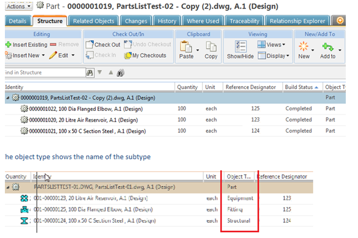
The structure created appears as follows:
Propagate AutoCAD Block Attributes on Part Usage Link Occurrences
Create the attributes to be published on Model Item uses link in Type and Attribute Manager and add those to Workgroup Manager Model Item uses link soft type and ‘Uses Occurrence Attributes’ soft type. To enable publishing of attributes on occurrences set Windchill preference, > > .
Creating an AutoCAD Block Part Structure Using Subtype Names
1. Create subtypes in Type and Attribute Management in the same manner as the previous section for subtype attributes.
The BlocksConfig.txt file will be modified.
Using the Custom BOM Sample File for Creating an AutoCAD Block Part Structure
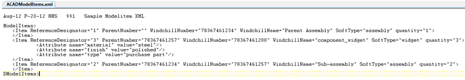
A custom BOM sample file ACADModelItems.xml is provided in the <WWGM Install Dir>\\libs\\i3libs\\resources\\acad\\Custom_BOM_Sample folder that can be used for creating an AutoCAD block part structure. The information for the part structure creation is available in the xml file.
| Set the preference Enable generation of a WTParts Structure from AutoCAD DWG files to Custom. |
The next figure shows the sample file.
The XML file contains an assembly, subassembly and subassembly component named component_widget. Model Item soft-type assembly and widget have been defined. Each entry also has a quantity. You need to create sub-types in Windchill called assembly and widget in > > . Attributes to be propagated on usage occurrence links have been defined as material, finish, and type.
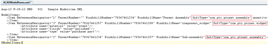
Edit Soft Type in the xml file by adding the full Internal Name of the Soft Type. In this example it is com.ptc.ptcnet.assembly and com.ptc.ptcnet.widget. Refer to the edited XML file shown in the next figure.
Add the XML file to WFS Workspace location. You can save the XML file to WFS Workspace location using any text editor after adding the editor application in wgmclient.ini file preference ‘wfs.add.applications’. Generating the XML file from AutoCAD with customization also allows the file to be saved to WFS Workspace location.
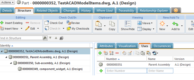
This example uses the file name TestACADModelItems.xml.
1. Create a file in AutoCAD and save it with the same XML file name without the extension. This new file will be TestACADModelItems.dwg.
2. Checkin the file using Custom Check-in with Auto Associate Parts to CAD Documents option.
As the part structure to be built is fetched from the XML file, the drawing will be empty. After checkin, theAutoCAD block part structure created will look as follows: