Managing Routing Plans
A routing plan is a manufacturing object that can be used in various scenarios, including validation. The routing plan object enables you to experiment with various scenarios before finalizing a process plan. For a process plan, you can create multiple routing plans. That is, you can associate multiple routing plans with a process plan.
Consider a scenario where you want to localize or run a process plan in your plant. You have two ways to evaluate the process plan for the time and cost. In such a case, a routing plan object is beneficial. You can create two routing plans to analyze and validate various structures or plans. You can use these two routing plans to perform localization in two different ways. For the first routing plan, you open the routing plan in Visualization, place the tools, check the ergonomic strategy, perform other tasks, and then get a result. You can perform similar tasks for the other routing plan. Then, you can compare the results to determine which routing plan better suits your business needs. This analysis helps in optimizing the process plan.
A routing plan requires a process plan, Bill of Material (BOM), and plant for its proper functioning. A routing plan acts as a link between these three entities.
You can use a routing plan as a production version. A routing plan determines which process plan should be used with which BOM for a specified quantity in a specific plant.
Optimizing the flow of material is an essential factor that contributes to improving productivity and reducing the manufacturing process cost. This flow could be related to how the material flows in the plant or how you route the manufacturing process plan in a plant. A routing plan enables you to define the flow of material or process plan in the plant and also optimize the flow and manage the artifacts, such as documents, processing resources, tools, and so on.
A routing plan helps you make the following decisions:
• Process to be followed based on quantity, date, lot.
• Tools, line, or work center to be used.
• How to utilize plant capabilities to optimize production if the quantity varies. For example, if the system must produce 100 quantities of Part A, it uses Process Plan 1, Line 1, Workstation 1, Operation 1, and Tool 1.
If it must produce 1500 quantities of Part A, it uses Process Plan 1, Line 1, workstation 2, Operation 1, and Tool 2. The system can also use a different process plan to produce 1500 quantities of Part A.
Benefits
A routing plan manufacturing object provides the following benefits:
• Enables you to try different scenarios before the actual production.
• Proactively validates the manufacturability of product designs, and reduces errors between engineering and production.
• Significantly reduces the time and cost spent on manufacturing activities.
• Improves productivity and user experience. With improved productivity and user experience, visualizing an actual manufacturing line that includes various manufacturing entities becomes easier.
Key Points
• A routing plan object contains the following information:
◦ Part that is going to be produced in a certain quantity
◦ The process followed while producing the part
◦ The plant used to produce the part
• A routing plan needs the following entities for its proper functioning:
◦ A process plan — contains the operation information.
◦ BOM — defines what needs to be produced.
◦ Plant — specifies which plant and line will be used to produce the actual component or product.
• Typically, a part is associated with a process plan and a routing plan. Ideally, to create and associate a process plan and a routing plan to a part, you must go to the part information page. The Related Objects tab on the part information page contains the Process Plans and Routing Plans table. With the help of actions available in the Process Plans and Routing Plans table, you create and associate the process plan and routing plan to a part. For more information, see Support for Products and Process Plans.
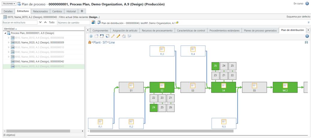
• A routing plan is a subset of a process plan. You can open the routing plan in the context of a process plan by using the Select routing list on the Structure tab of the process plan information page. For more information, see Opening a Routing Plan in the Process Plan Browser.
You can also open the routing plan and the associated manufacturing structures by using the Open in Plant Layout, Open Related Upstream in Plant Layout, or Open as Upstream in Plant Layout action. For more information, see Opening Manufacturing Structures Associated with Routing Plan.
• When you revise a process plan independently, the process plan and routing plan become out of sync. The system displays an out of date  indicator if the routing plan and process plan are not in sync. If the process plan and routing plan are out of sync, the system does not allow you to localize operations. Operations can be localized only if the process plan and routing plan are in sync.
indicator if the routing plan and process plan are not in sync. If the process plan and routing plan are out of sync, the system does not allow you to localize operations. Operations can be localized only if the process plan and routing plan are in sync.• In the Routing Plan tab, the system displays the line information for the lines related to the routing plan. If you do not specify any line when creating a routing plan, then the system displays the information for all the lines. For more information, see Inserting A New Routing Plan from BOM Transformer.
• The process plan identity appears above the PPB toolbar.
• The routing plan identity appears above the process plan tabs. The checked out icon next to the routing plan object name also appears if the routing plan is checked out.
• You can associate multiple routing plans with a process plan.
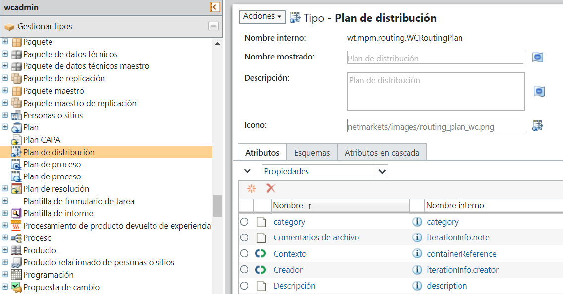
• The Type and Attribute Management utility contains the following entities related to a routing plan:
◦ Routing Plan
◦ Routing Artifact
▪ Routing Resource Artifact
◦ Routing Node
▪ Routing Node Group
▪ Routing Feeder Line
▪ Routing Station
▪ Routing Work Cell
▪ Routing Zone
▪ Routing Operation
For more information, see Working with the Type and Attribute Management Utility.
• The following layouts are available for a routing plan:
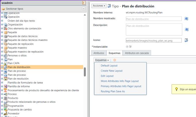
You can customize the layout and add new attributes according to your business requirement. For more information about attribute layout, see Layouts Tab and Editing Attribute Layouts.
• A routing plan object also supports cascading attributes.
• You can filter the localized information based on the configuration specification applied to the process plan. Consider the following scenario:
A process plan has multiple routing plans associated with it. The operations are localized with respect to a specific routing plan. In such a case, if you apply variant specifications, then the system filters the localized operations based on the configuration specification applied to the process plan.
• Use the Reconcile Routing Plan action to synchronize attribute values from the process plan operations to the localized operations. This action ensures consistency across the process plan and its localized operation with respect to the routing plan. The system also supports the selective exclusion of operations from synchronization. For more information, see Reconciling a Routing Plan.
• Use the  Save As action to create a copy of an existing routing plan. The Save As action allows you to duplicate an existing routing plan and create a new one based on the original. When you use this action, the system carries forward essential information from the source routing plan, including localized operations, reference documents, and attributes such as setup time, labor time, queue time, and processing time. You can provide a new name and location for the duplicated routing plan during this process. For more information, see Using the Save As Action for a Routing Plan.
Save As action to create a copy of an existing routing plan. The Save As action allows you to duplicate an existing routing plan and create a new one based on the original. When you use this action, the system carries forward essential information from the source routing plan, including localized operations, reference documents, and attributes such as setup time, labor time, queue time, and processing time. You can provide a new name and location for the duplicated routing plan during this process. For more information, see Using the Save As Action for a Routing Plan.Terminology Used in Routing Plan Features
The following terms are specific to the routing plan functionality in MPMLink.
Term | Definition |
|---|---|
Zone | A zone-based manufacturing approach is applied to manufacturing processes at an assembly line's workstation. Consider a workstation where the process of assembling four car doors is taking place. Four different operators are engaged at the same station. The operators are assembling the left front, right front, rear left, and rear right doors, respectively. In such scenario, the workstation can be considered to be virtually divided into four zones, where each zone consists of different operations being performed. You can allocate different operations to the different zones. For more information, see Adding a Zone in the Routing Plan Tab. |
Side and Level Attributes | Attributes defined for a Workcenter. These two attributes are most effective when working with zones. The Side attribute is only applicable for a feeder line and zones. That is, the system uses the value set for the Side when dealing with a feeder line or zones. The Level attribute is used by the system when it deals with zones. For more information, see Adding a Zone in the Routing Plan Tab and Using the Side and Level Attributes. |
Workcenter | A physical resource or a set of resources that can be assigned to an operation (for example, lines, work units, work cells, resource pools, workstations, and feeders). |
Feeder Line | A secondary assembly line that provides parts for use in a primary assembly line. |
For more information, see the following topics: