Control Characteristics
In a process, part, assembly, or system, control characteristics are any functional features, geometrical or material properties, that can be qualified, measured, or quantified and for which variation or deviation control is necessary.
Use the Control Characteristics tab to view and add control characteristics, as well as manage the resources allocated to a control characteristic. Different options are available, depending on the object selected in the structure pane:
• If a part or process plan is selected then use this tab to create control characteristics
• If an operation is selected then use this tab to allocate control characteristics and resources to other control characteristics
Available Actions
The following table explains the actions available from the toolbar on this tab:
|
Icon
|
Action
|
Description
|
|---|---|---|
 |
Insert Existing
|
Adds an existing control characteristic.
|
 |
Insert New
|
Adds a new control characteristic.
|
 |
Remove Standard Control Characteristic
|
Removes the selected control characteristic from the part or operation to which it was allocated.
|
|
Copy Standard Control Characteristic
|
Copies the selected control characteristic to the clipboard.
|
|
|
Duplicate and Paste Control Characteristic
|
Duplicates and moves the control characteristic on the clipboard to the designated location.
|
|
 |
Paste
|
Moves the control characteristic on the clipboard to the designated location.
|
 |
Update Model Item
|
Searches for and selects a new model item that is to be associated with the control characteristic.
|
 |
Show Search Bar/ Hide Search Bar
|
Use to search a control characteristic from a list of control characteristics.
|
 |
Table views (Default)
|
Customizes the table views.
|
Attributes in Control Characteristics Tab
The following attributes are present in the Control Characteristics tab of BOM Transformer:
• Number
• Name
• Severity
• Description
• Model Item Graphical Representation
• Version
• Context
You can edit the values Severity and Description of a control characteristic inline. If a model item is associated with a control characteristic, then the information about the model item is displayed in Model Item Graphical Representation.
Model Item Graphical Representation on the Control Characteristic Tab
You can add a control characteristic in the control characteristic tab by using the following operations:
• Insert Existing
• Insert New
• Paste
The information displayed in the Model Item Graphical Representation attribute varies based on the selection.
• If there is no model item associated with the part, attribute is blank.
• If there is only one value that meets the criteria, attribute shows the default value.
• If there are multiple values, by default the record shows blank for this attribute. The system launches the Select Model Item dialog box from which you can assign model item to a cc record. Select a model item from the Model Item ID drop down list for a given record. You are required to perform this selection for each record of the control characteristic for a specified category. A model item can be assigned only once to a cc record. If no model item is selected, then the filed will be blank. If all but one model item remains to be assigned, this model item is automatically assigned to the next record you create for this control characteristic.
• Standard Control Characteristics follow the quantity of measure defined in the Windchill system.
To learn more about the measurement systems, see the following topics:
The Model Item Graphical Representation column of the BOM Transformer displays values based on the unit set in the Measurement System preference. Consider the following use case:
1. Multiple model items are associated with a CAD part NX_PMI_Dimension. The model items are of different types.
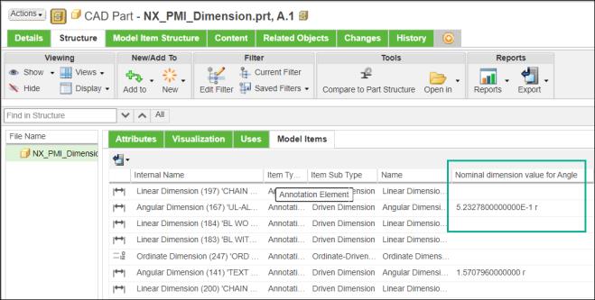
Note that for the model item Angular Dimension (167), the value of the Nominal dimension value for Angle attribute is displayed in radians.
2. A part Engine1 of type wtpart is also associated with the CAD part NX_PMI_Dimension.
3. Set the value of the Measurement System preference to USCS.
To learn more about the Measurement System preference, see Displaying Attribute Values with Units.
4. Based on the set value, the attribute values change accordingly.
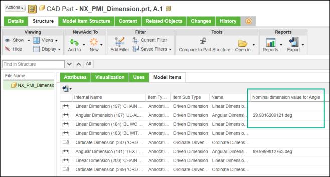
The value of the Nominal dimension value for Angle attribute is now displayed in degrees.
5. Open part Engine1 in the BOM Transformer.
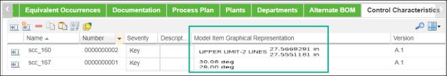
6. Create a new standard control characteristic scc_167 with the same Category as that of model item Angular Dimension (167).
7. In the Control Characteristics tab, select scc_167 and then select the model item ID as Angular Dimension (167).
8. For scc_167, the Model Item Graphical Representation column displays the value in degrees. This is because, the value of the Measurement System preference is set to USCS.
The value displayed in Model Item Graphical Representation column is also displayed at the following locations: • Information page of the CAD part • Control Characteristics table in the information page of the part • Process Plan Browser • Work Instruction • Related tab of operation |