Change Examples
The following examples illustrate the configuration level change management process.
Change Example 1: Basic Configuration Level Change Management Process
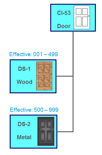
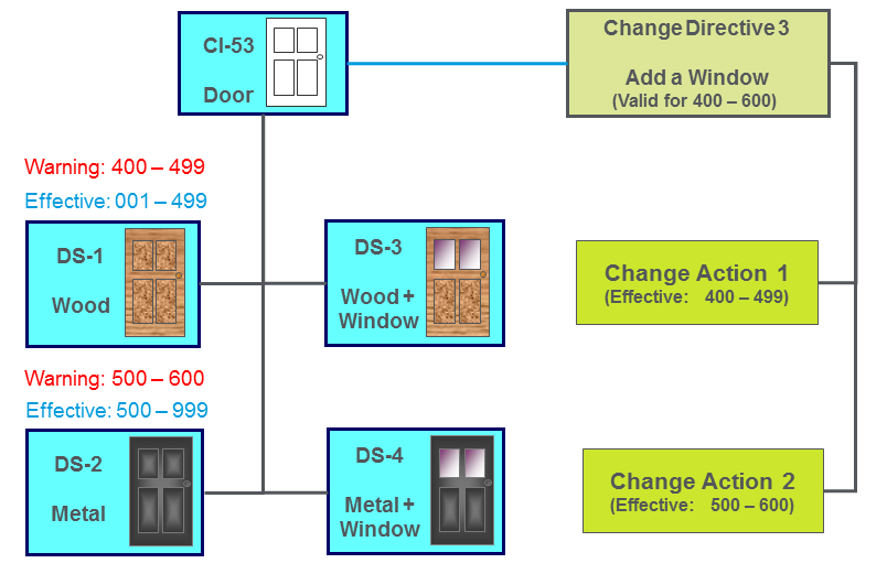
The following example uses a product structure design with a configuration item (CI-53), which is a simple door. The following two design solutions have been implemented for this configuration item:
• DS-1: Effective for serial numbers 001 – 499.
• DS-2: Effective for serial numbers 500 – 999.
A necessary change to the product structure is identified. This change affects the door configuration item by requiring a window for the serial number range 400-600. The following change process addresses this change:
1. The user creates a change directive that affects the door configuration item. The new change directive requests that the door includes a window for the serial number range 400-600 of the product.
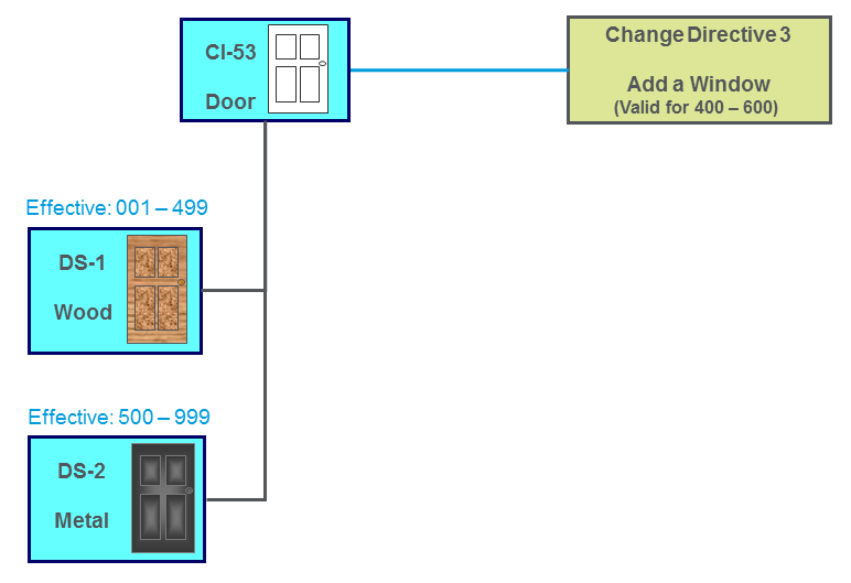
This change directive affects a section of the effectivity range for both existing design solutions, DS-1 and DS-2.
2. The user selects the Generate Change Actions action and the system generates two change actions to address the change directive:
◦ Change Action 1—Represents the need for a new design solution to implement a wooden door with a window for serial numbers 400-499 of the product.
◦ Change Action 2—Represents the need for a new design solution to implement a metal door with a window for serial numbers 500-600 of the product.
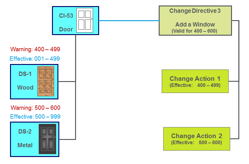
3. The system displays effectivity warnings for the existing design solutions, DS-1 and DS-2:
◦ The warning for DS-1 indicates that it might no longer be applicable for serial numbers 400-499.
◦ The warning for DS-2 indicates that it might no longer be applicable for serial numbers 500-600.
4. The user responsible for the affected configuration item (CI-53) creates two design solutions to address the system-generated change actions:
◦ DS-3—Wooden door with a window
◦ DS-4—Metal door with a window
You add design solutions from the Design Solutions table of the configuration item. As a result, the design solution is associated with that configuration item and can fulfill related change actions. |
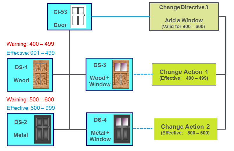
5. The user solves the change actions by fulfilling them with the new design solutions:
◦ DS-3 fulfills Change Action 1
◦ DS-4 fulfills Change Action 2
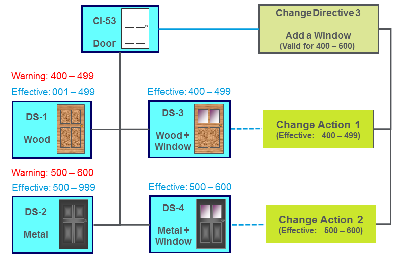
6. The system sets the effectivity ranges for the new design solutions that fulfill the change actions:
◦ The effectivity for DS-3 is set to 400-499
◦ The effectivity for DS-4 is set to 500-600
7. The system removes the effectivity warnings for the pre-existing design solutions and adjusts their effectivity ranges:
◦ The effectivity for DS-1 is adjusted to 001-399
◦ The effectivity for DS-2 is adjusted to 601-999

Change directives and the change actions generated from them sometimes affect overlapping effectivity ranges. In these cases, effectivity ranges for design solutions that have fulfilled change actions sometimes need to be modified (as in the case of DS-1 and DS-2 in the above example). A history of this stacking of change directives and change actions is displayed in the Modification Stack table. For information, see About Modification Stack Tables. |
Change Example 2: Multiple Design Solutions for a Change Action
Although only one design solution can fulfill a change action, multiple design solutions can be associated with a change action. These alternate design solutions are called candidates. This is helpful in order to keep a history of design solutions that are considered candidates to fulfill the change action. Additionally, any design solution associated with a change action can be changed from a candidate design solution to the design solution that fulfills the change action.
Scenario 1: Selecting One of Several Candidate Design Solutions
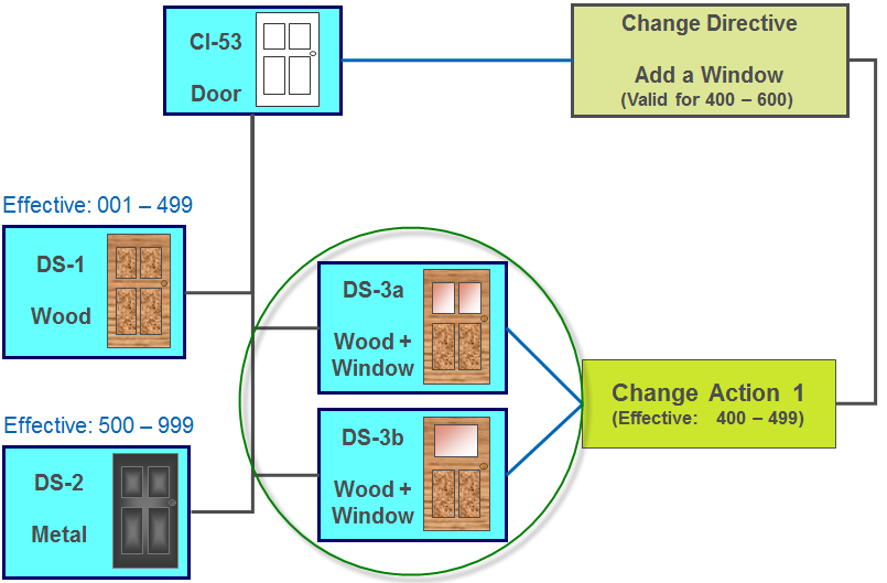
The following example continues the simple door design and illustrates the change process in which several design solutions are considered as possible candidates. After analysis, only one of the design solutions is selected as the one to fulfill the change action. The system keeps track of the candidate design solutions that are considered in the analysis process.
1. The user creates two design solutions (DS-3a and DS-3b) as candidate design solutions for a change action (Change Action 1). Each design solution has aStage of Candidate.
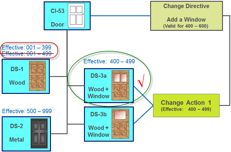
2. The user analyzes the candidate design solutions, performs the Fulfill Change Action action, and then selects the desired design solution (DS-3a). The design solution is updated with the effectivity range that the change action addresses (400-499). The selected design solution (DS-3a) moves to the Fulfilled stage and the change action is updated with the Solved status. The other candidate design solution (DS-3b) remain in the Candidate stage.
Scenario 2: Performing Undo Fulfill Change Action and Selecting a Different Design Solution
When a change action moves from the To be studied status to Solved, candidate design solutions can no longer be added or removed from the change action.
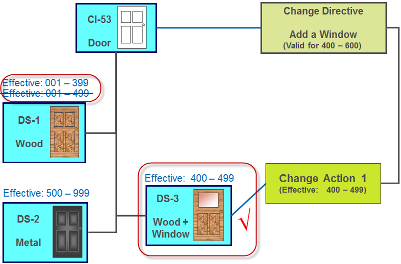
If, at a later date, a new design solution should become a candidate and replace the existing design solution that fulfills the change action, you must perform the Undo Fulfill Change Action action.
1. On the applicable change action (Change Action 1), the user selects the Undo Fulfill Change Action action.
The change action moves from the Solved status to To be studied. The design solution (DS-3) that was previously used to solve the change action moves from Fulfilled back to Candidate.
2. The user adds or removes any necessary candidate design solutions. In this example, design solution DS-3a is added.
3. The user performs the Fulfill Change Action action and selects the desired design solution (DS-3a).

The change action status changes from To be studied to Solved. The previous design solution (DS-3) remains in the Candidate stage, and the new design solution (DS-3a) changes to Fulfilled. The selected design solution (DS-3a) is updated with the effectivity range that the change action addresses.