Creating Graphical Representations in the Process Plan Flow Tab
The Process Plan Flow tab provides a visual representation of the process plan structure, which could be difficult to understand from the tree structure alone. It helps to visualize operations, sequences, and their relationships, making it easier to allocate parts and understand the flow. This representation includes the following:
• Starting point
• Operations
• Sequences
• Ending point
Tutorial
This tutorial describes the following:
• How to create process plan flow diagrams
• How entities, such as operations, are represented in the Process Plan Flow tab
Perform the following steps:
1. Create a process plan pp1.
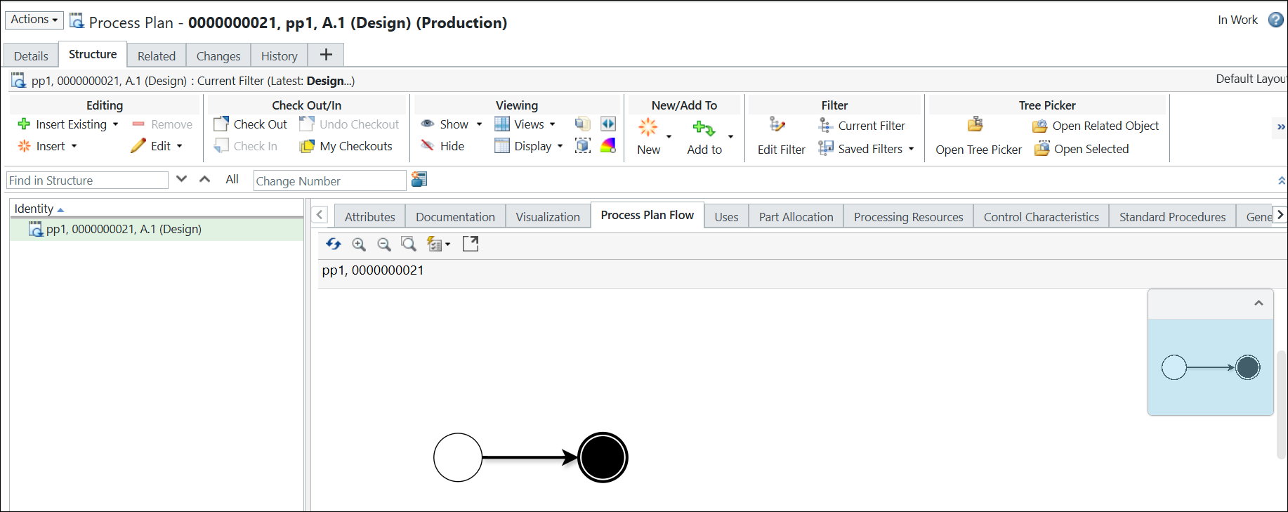
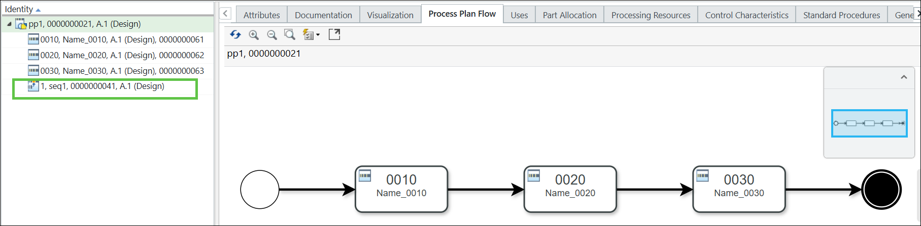
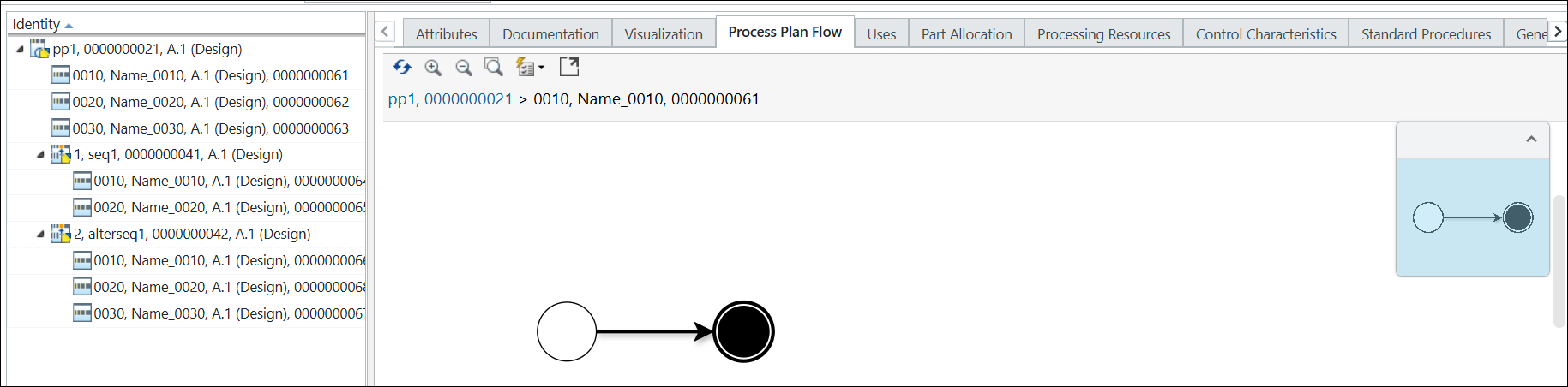
2. Open the process plan pp1 in the process plan browser. The following structure appears in the Process Plan Flow tab:
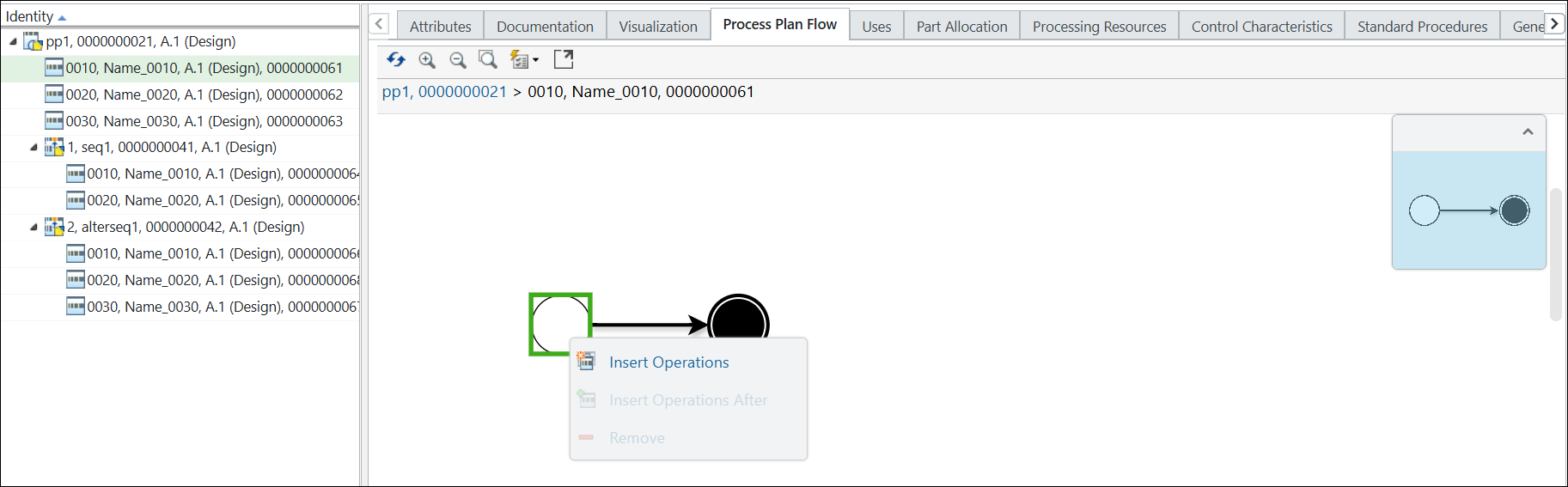
3. In the Process Plan Flow tab, select the start point. Right-click and select Insert Operations .
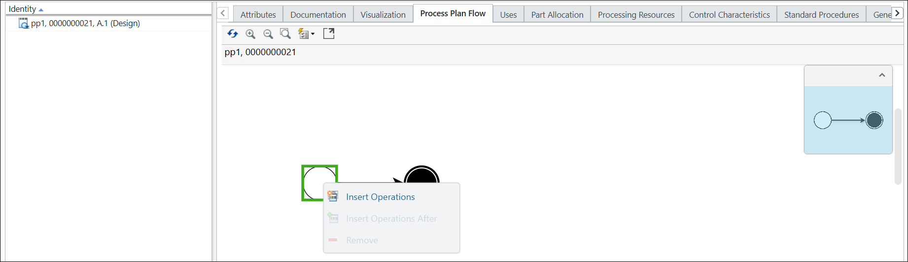
The Insert Operations dialog box opens.
4. Enter the number of operations that you would like to create. For example, 3.
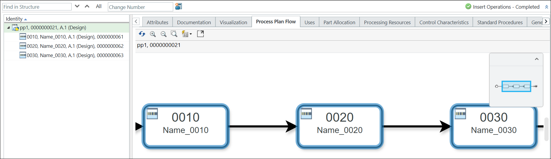
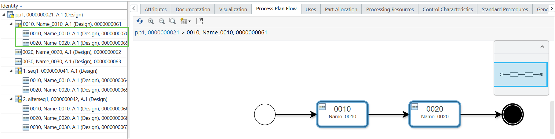
5. Click OK. The Insert Operations dialog box closes, and the operations appear in the Process Plan Flow tab and the process plan tree structure.
The newly added operations are highlighted in blue. |
6. Select the process plan pp1 in the process plan tree structure.
7. Add a parallel sequence under the process plan pp1. The sequence appears under the process plan pp1 in the process plan tree structure. For more information, see Creating Sequences.
8. Insert operations under the parallel sequence using the > action available in the Editing section.
The following structure appears in the Process Plan Flow tab:
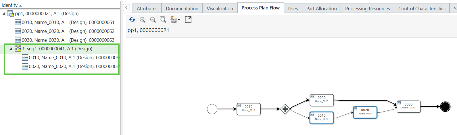
For more information, see Creating Operations.
You can now add new operations in the sequence using the Insert Operations After action. |
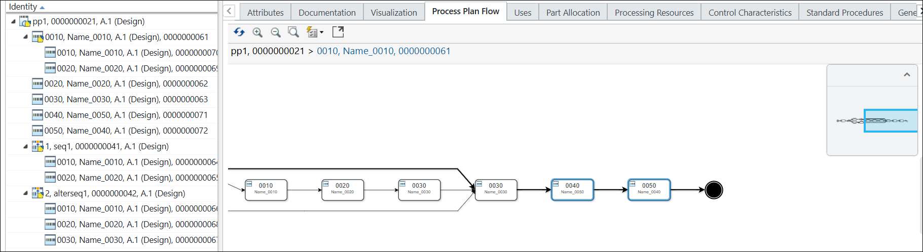
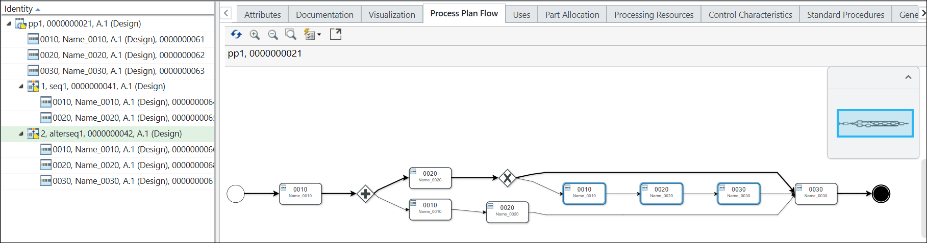
9. Add an alternate sequence under the process plan pp1. The alternate sequence appears under the process plan pp1 in the process plan tree structure.
The following structure appears in the Process Plan Flow tab:
10. Select operation 0010 in the process plan tree structure.
11. Right-click and select > .
The following structure appears in the Process Plan Flow tab.
As there are no sub-operations present under the operation 0010, the Process Plan Flow tab displays only the start point and end point. |
12. In the Process Plan Flow tab, select the start point. Right-click and select Insert Operations .
The Insert Operations dialog box opens.
13. Enter the number of operations that you would like to create. For example, 2.
14. Click OK. The Insert Operations dialog box closes, and the operations appear in the Process Plan Flow tab and in the process plan tree structure.
The newly added operations are added under the operation 0010 in the process plan tree structure. |
15. Select the process plan pp1 in the process plan tree structure.
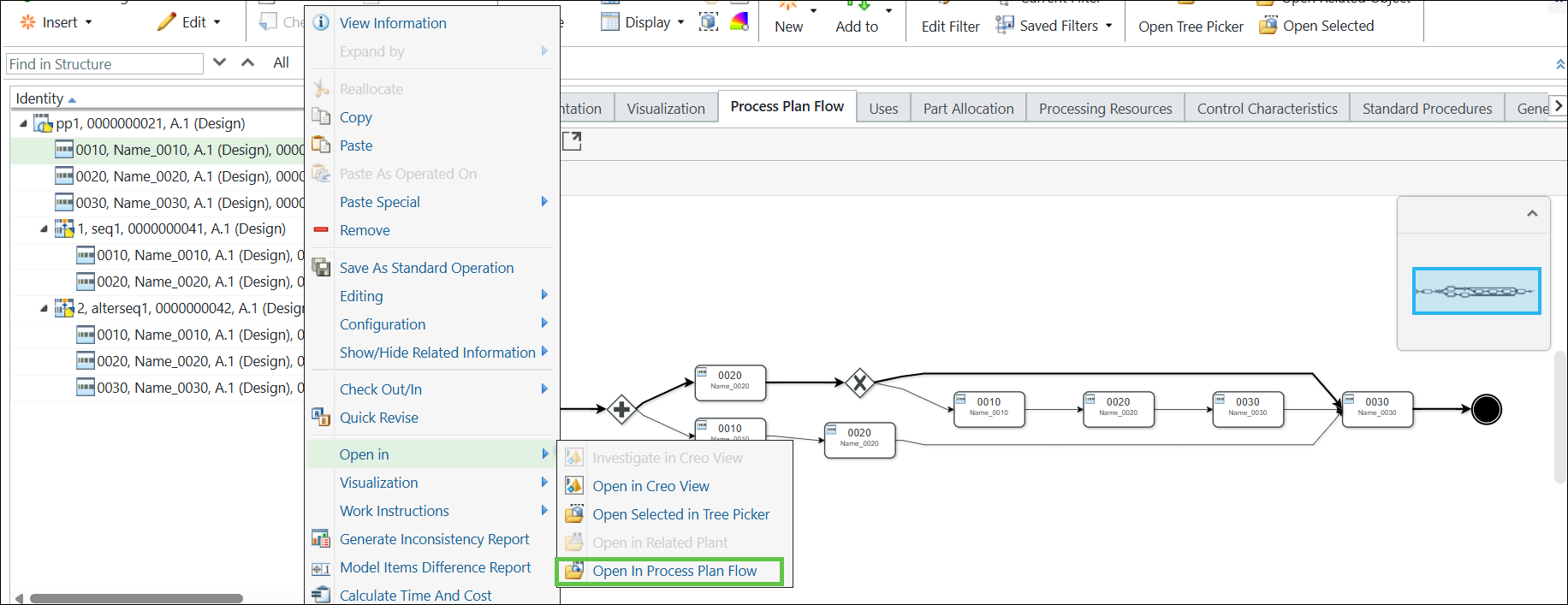
16. Right-click and select > . The following structure appears in the Process Plan Flow tab.
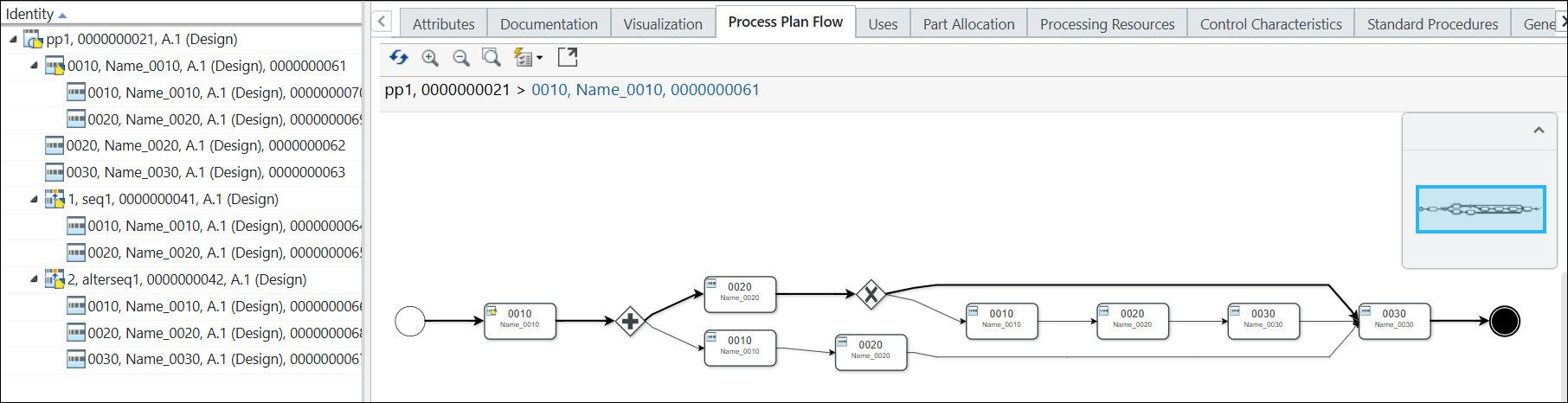
The operations added under the operation 0010 do not appear in the Process Plan Flow tab because only the first level of operations is displayed by default. To view these operations, you must select the operation 0010, right-click, and select > to view the detailed representation. |
17. Select operation 0030. Right-click and select Insert Operations After.
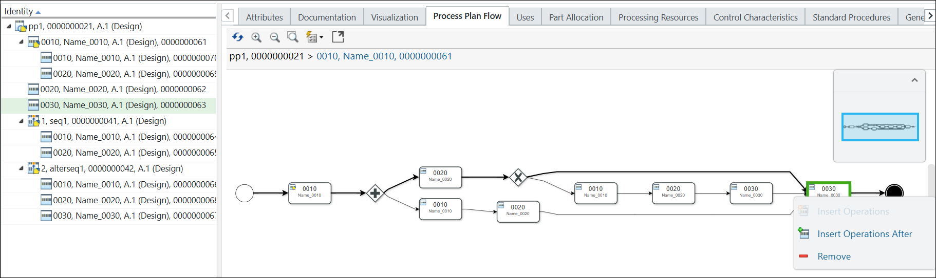
The Insert Operations After dialog box opens.
18. Enter the number of operations that you want to add after operation 0030. For example, 2.
19. Click OK. The Insert Operations After dialog box closes, and the operations appear after operation 0030 in the Process Plan Flow tab. The system also highlights the newly added operations.