Create a Disassembly Sequence in Creo Illustrate
Industrial AR is often used for assembly/disassembly sequences, and these sequences are created within Creo Illustrate. Creo Illustrate allows you to create animations for CAD models with the help of their model structure. The tools featured in this next tutorial are Transform, Phantom, Flash, and Fly Out and will be used to remove the front left motor of the quadcopter. You can use the skills learned in this section to add animated sequences for the rest of the parts on the quadcopter.
1. Navigate to the Figures tab in the primary panel, hover over Figure 1, then right-click and select Rename. Rename the figure to fig1-rotorFL. Renaming the figure helps differentiate between multiple sequences.
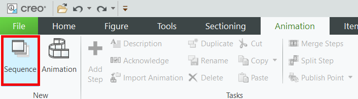
2. To create a step-by-step animation for AR, a sequence must be added to the Creo Illustrate file. To add a sequence, navigate to the Animation tab and select Sequence from the New section in the ribbon.
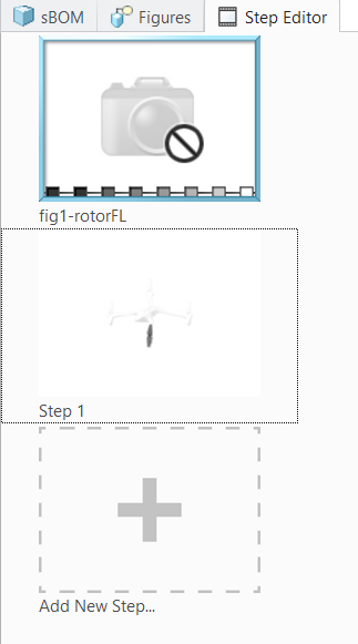
3. The Step Editor appears in the primary panel with an initial structure that looks like the image below. Each step in the sequence features a separate animation. When these steps are played at the same time, they create a comprehensive sequence for disassembling the motor from the rest of the quadcopter.
4. Before starting a sequence, ensure that Record Content is selected in the Animation tab. The red circle in the corner of the screen signifies that this feature is active, and that all changes made to the model during the step are being recorded. If Record Content is not selected, the changes will not be recorded for playback.
5. Now, you’ll create a sequence animation that shows the motor being removed.
a. Click Step 1 in the Step Editor to begin editing the step. The lower data panel appears. This panel consists of the following tabs:
▪ Keyframe Editor
▪ Item List
▪ Description
▪ Resources
▪ Localization
▪ Attributes
This panel is used to edit the animated sequence of the model.
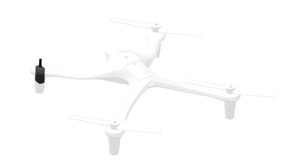
b. Select the visible rotor and open the Effects drop-down in the Animation tab. Select the Flash effect and a color.
| If Flash is not available as an option in Effects, make sure that Step 1 is selected in the Step Editor. If fig1-rotorFL is the selected frame, the Flash effect will not be available. |
c. Playback controls for the step appear. This lets you play the step in its current form and move around to a certain point in time.
The Keyframe Editor provides you with advanced controls for animations that allow you to edit the location, transparency, visibility, and color of a given part. It also allows for time editing of the step, which can be used for making a certain effect longer or shorter within the step, among other things.
d. With the same rotor selected, open the Effects drop-down again. This time, select the Fly Out effect. This effect will left the rotor off the assembly and fade out. To make the rotor fly upwards, select the +Y direction when prompted.
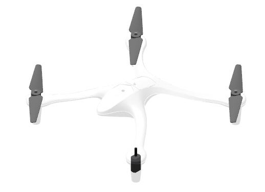
e. This completes the animation for Step 1. The model should currently look like this:
| If desired, the playback controls can be moved back in time to edit incorrect portions of a sequence. For example, after Step 1 has been completed, the step will be two seconds long. The 1st second will be for making the rotor flash and the 2nd second will be of the rotor lifting and fading out. If the fade out is incorrect, you can either use the Undo button, or drag the playback control to 1 second into the step and just rerecord the action to overwrite the previously recorded motion. |
6. Next, create a sequence animation to remove the remaining rotors.
a. Click Add New Step in the Step Editor to create a new step for the sequence. This creates a new frame named Step 2 and will start where Step 1 left off.
b. After removing the front left rotor, the three remaining rotors need to be removed. Even though they are in phantom view, they still need to be removed in order to continue the process of taking the top of the quadcopter off to reveal the motor. The rotors are going to flash before they are lifted off, and in order to do that, they must become visible again. Select the other three rotors by clicking them while holding down Ctrl + Alt. Holding the Alt key makes it possible to select parts that have been made phantom. In the Parts tab, click Edit Figure Phantom to turn off phantom for the rotors.
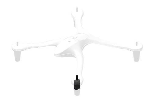
c. With the three rotors selected and visible, navigate back to the Effects drop-down and select the Flash effect. Like the first rotor, use the Fly Out effect to make the other three rotors fly up and fade out.
7. The next step in the sequence will be to take off the battery cover and the top of the quadcopter.
a. The last step that needs to be completed before the top of the quadcopter is taken off to reveal the motor is to take off the battery cover. Click Add New Step.
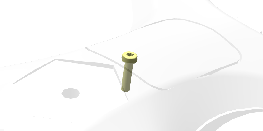
b. Since the screw for the battery cover must be removed but is small and can be easily overlooked, it should be highlighted to make it more visible. In the sBOM tab, select the screw named ISO14580-M2_5X10-4_8.PRT that is at the location shown (there are two instances of the part that are close together), and use Edit Figure Phantom to make it visible.
c. Use the Flash effect to make the screw flash, and then use Fly Out in the +Y direction to remove the screw.
d. Repeat the process of using the Edit Figure Phantom button to reveal the part, flashing using the Flash effect, and making the part fly away using the Fly Out effect in the +Y direction for the QUADCOPTER-BATTERY-COVER and QUADCOPTER-TOP parts.
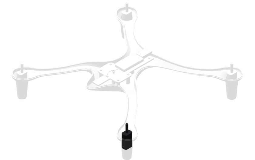
8. The last step in the sequence is removing the motor.
a. Click Add New Step.
b. Now that the front left motor has been exposed, it can be removed for inspection. Use the Flash effect on the motor.
c. Use Fly Out to remove the motor. This completes the procedure for disassembling the quadcopter so that the motor can be accessed and removed.
9. Using what you’ve learned so far, create five more disassembly sequences in the same .c3di file for:
◦ Removing the other three motors and rotors (front right, back left, back right) in the same way that the front left section was removed
◦ Removing the battery pack
◦ Removing the entire top section of the quadcopter
The completed
quadcopter101.c3di file provided in GitHub can be used as a reference for all of the disassembly sequences.
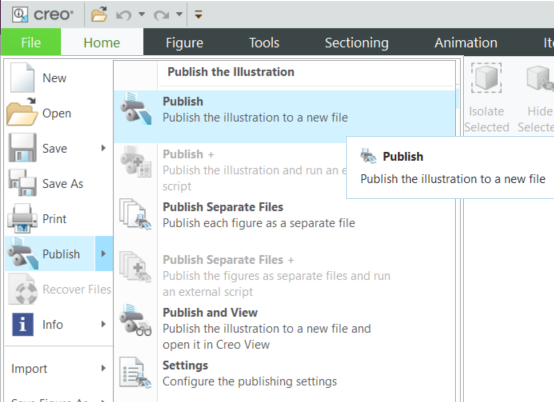
10. From the File tab, select Publish. Publishing a .c3di file allows it to be exported as a .pvz file. Save the published file as quadcopter.pvz. This file will be used in Vuforia Studio in the next part of this project.