Add Attributes to the Model
Attributes allow you to access different types of metadata that is associated with a model. In this case, attributes are being added that will be accessed inside Vuforia Studio in a later part of the project. This section shows you how to add those attributes to a model and prepare the model for the next section of this activity. The attributes being added are part numbers for part recognition in the AR experience, and sequence identifiers to differentiate between sequences. These sequences will be performed on the different sections of the quadcopter.
|
|
A completed .c3di file named quadcopter101.c3di is available in GitHub. The file contains all attributes that will be added in this section. |
1. If not already visible, open the lower data panel to reveal the Attributes tab.
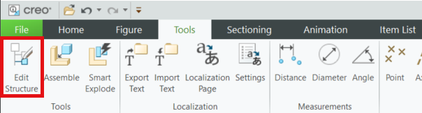
2. From the Tools tab, select Edit Structure.
3. Click OK on the Edit Structure pop-up since your intent is to edit the sBOM structure and animations haven’t been created yet.
4. Select the checkbox next to the name of the model to make it visible. Once it becomes visible, it will be blue.
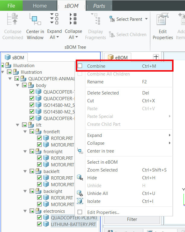
5. Right-click in the sBOM tab and select > to expand the sBOM to show all parts in the assembly. Do the same with the eBOM.
6. Select both QUADCOPTER-PCB.PRT and LITHIUM-BATTERY.PRT in the sBOM.
a. With the two parts selected, right-click over them to open a pop-up menu. Select the Combine check box from the menu. This combines the two parts since they can only be serviced together at the same time. In this case, when purchasing the quadcopter, you must buy the entire electronics kit as a single part; you cannot buy the PCB and battery separately, which is why they are combined in the sBOM.
b. You should notice a difference in the sBOM, with the electronics assembly now listed as a single part instead of an assembly. The icon next to QUADCOPTER-PCB.PRT and LITHIUM-BATTERY.PRT the should now show that they are combined parts.
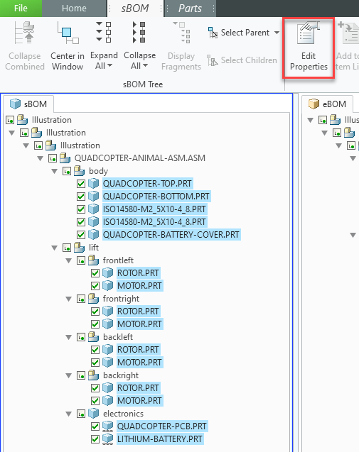
7. Select all the parts in the sBOM which should now include the electronics as a standalone part.
8. With all parts selected in the sBOM tab, open the sBOM tab in the ribbon and select Edit Properties.
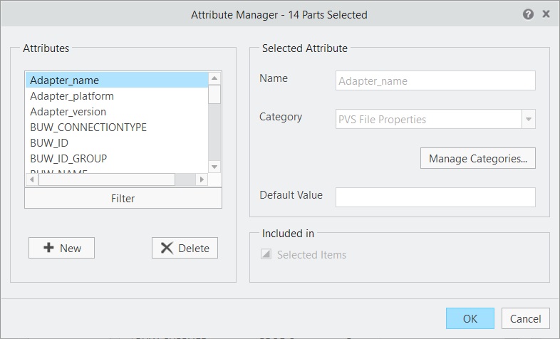
9. In the Part Properties window that appears, click Attributes.
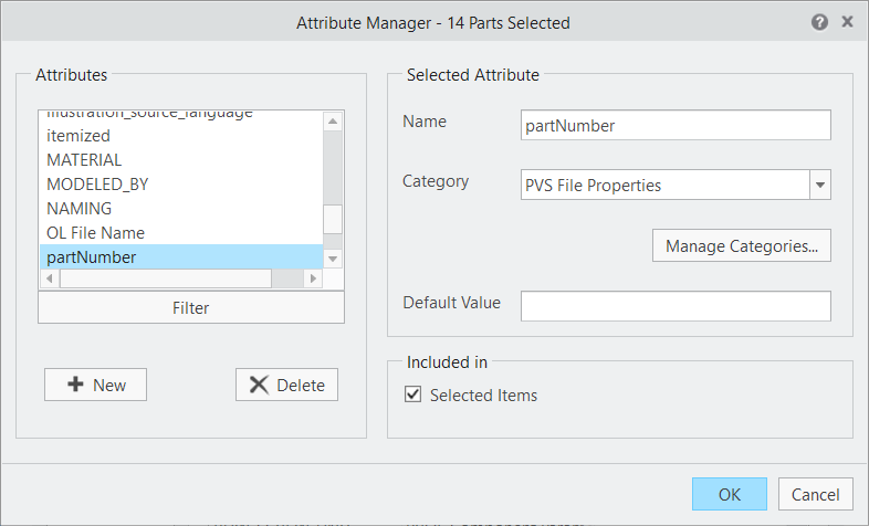
10. Select Manage Attributes... at the bottom of the window. When the Attribute Manager window opens, click + New. The Add New Attribute window opens.
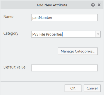
11. Enter the following information in the Add New Attribute window and then click OK:
◦ Name—partNumber
| Part numbers are important in the manufacturing process, as they help differentiate between parts. In terms of attributes in Illustrate, each part in the sBOM is an individual instance of a part, but the same part can be used more than once. Each instance of a part will have a unique Feature ID, but the part number will be the same for the parts. ROTOR.PRT will always have a partNumber attribute of Rotor-1234, but the Feature_Id attribute will vary for each instance that it is placed in the model. If a different rotor were to be placed in the model, then it could have a part number of Rotor-6789, which would differentiate between the different rotors. |
◦ Category—select PVS File Properties
◦ Default Value—leave this field blank
12. The Attribute Manager appears again. Under Included in, make sure that the Selected Items checkbox is selected.
13. Create another attribute and name it Illustration. Select PVS File Properties as the Category, and leave Default Value blank. This new attribute will contain the property that ties a figure to an illustration sequence. Include this for all items. When finished, click OK and close the Attribute Manager.
14. Close the Part Properties window.
15. If the new attributes were created successfully, the new properties for partNumber and Illustration should appear at the top of the Attributes list for the parts that they were added to when a part is selected in the sBOM. If they do not appear at the top of the list, go back and ensure that when the parts were selected and that the attribute was included for all parts.
16. Attributes can be edited while the Attributes tab is open in Structure Edit mode. When a part is selected, the header of the tab changes from Attributes to the name of the selected part. Double-click on an attribute to open the Attribute Detail window that displays the Category, Name, and Value of the attribute.
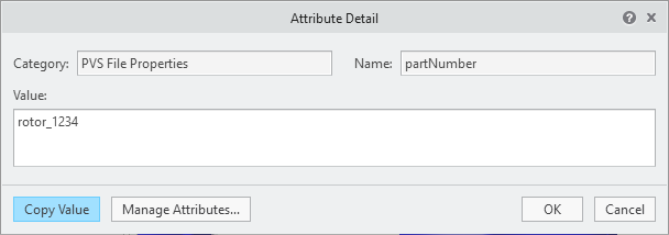
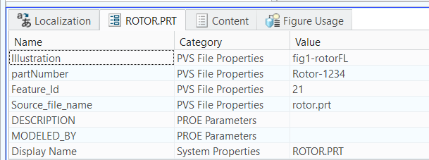
a. Select ROTOR.PRT in the frontleft assembly in the sBOM tab.
b. Double-click the partNumber attribute in the Attributes tab (which has now changed its header to ROTOR.PRT to reflect the selected part). This opens the Attribute Detail window.
c. Enter Rotor-1234 in the Value box. Click OK.
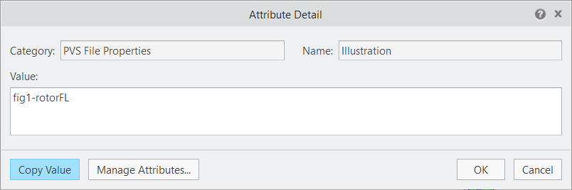
d. Double-click the Illustration attribute in the ROTOR.PRT tab and enter fig1-rotorFL. Click OK. These attributes will be used in the accompanying Vuforia Studio experience.
e. For the MOTOR.PRT part in the same frontleft subassembly, add a value of Motor-5678 for the partNumber and fig1-rotorFL for Illustration. In this case, a different part is being used, but since it is part of the same illustration sequence, it will share a similar property with ROTOR.PRT.
| If there were another figure created to illustrate the front-right rotor being taken off, the ROTOR.PRT part in the frontright assembly would have a partNumber of Rotor-1234 like the other rotor since they are the same CAD part. But, because ROTOR.PRT would be located in the front-right, it would have an Illustration attribute of fig2-rotorFR since it is part of a different sequence. |
17. Once you’ve added the attributes, the Attributes tab should look similar to this:
18. The new attributes have now been added to a part. Continue this process for each of the parts in the model listed in the table below. If a part is not part of an animation in the design, then it will not have a value for the Illustration property.
| All sBOM depths are under the same path of Illustration > Illustration > QUADCOPTER-ANIMAL-ASM.ASM |
sBOM Depth 4 | sBOM Depth 5 | sBOM Depth 6 | partNumber | Illustration |
body | | | | |
| QUADCOPTER-TOP | | qc-top-1111 | |
| QUADCOPTER-BOTTOM | | qc-base-1111 | |
| ISO14580-M2_5X10-4_8 | | bolt_4321 | |
| ISO14580-M2_5X10-4_8 | | bolt_4321 | |
| QUADCOPTER-BATTERY-COVER | | qc-cover-1111 | fig6-battery |
lift | | | | |
| frontleft | | | |
| | ROTOR | rotor_1234 | fig1-rotorFL |
| | MOTOR | motor_5678 | fig1-rotorFL |
| frontright | | | |
| | ROTOR | rotor_1234 | fig2-rotorFR |
| | MOTOR | motor_5678 | fig2-rotorFR |
| backleft | | | |
| | ROTOR | rotor_1234 | fig3-rotorRL |
| | MOTOR | motor_5678 | fig3-rotorRL |
| backright | | | |
| | ROTOR | rotor_1234 | fig4-rotorRR |
| | MOTOR | motor_5678 | fig4-rotorRR |
| electronics | | electronicspack-3333 | fig5-all-lift |
| | QUADCOPTER.PCB | pcb_1357 | fig5-all-lift |
| | LITHIUM-BATTERY | battery_2468 | fig5–all-lift |
19. To close out of the Structure Edit interface, go to the Home tab in the ribbon and select Close Edit on the right-end of the ribbon.
20. Open the File tab and click Save. Save the file as quadcopter. This creates a .c3di file. Later, this file will be exported as a .pvz file, which is the format that can be read by Vuforia Studio.