Add New Route
General
Click  in the action toolbar to create a new route. The Add New Route display will load.
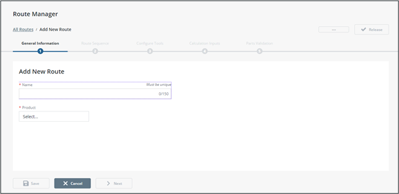
The navigation band across the top of the display indicates your current step in the process.
At any time, you can click All Routes in the breadcrumb trail or click Cancel to return to the route list. All unsaved information will be lost.
Step One: General Information
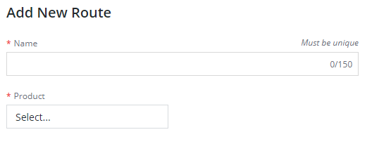
1. Enter a unique name for the route.
2. Assign one or more products to be assembled on the route. These are the final products made when route has completed execution.
a. Click Search products to open the advanced product selection pop-up.
Only final products made once route has completed execution will display. |
b. Select one or more products by adding them to the selection list on the right side of the advanced product selection pop-up.
c. Click Confirm.
When a route is assigned to more than one product, work instructions with parts validation steps cannot be added to the route. |
3. Click Save to save the route and stay on Step One, or
4. Click Next to save the route and go to Step Two.
Once saved, Step Two: Route Sequence can be navigated to and configured.
Step Two: Route Sequence
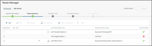
This step will define the production path the product will take during assembly. The grid lists stations/work cells and their associated work instructions.
• The production point is indicated by  . This is where production quantities will be counted as good production. The production point will be automatically assigned to the last sequence item on the route.
• A routing item that will report production (see CWC Configuration Guide, Production Endpoint) is indicated by 
• Auto-advance stations are indicated by  .
.
• Work instructions that do not require additional configuration are indicated by  . An
. An  indicates that additional configuration must happen before the route can be used.
indicates that additional configuration must happen before the route can be used.Adding a Sequence Item
1. Click Add to launch the New Route Sequence Item pop-up.

2. (Optional) Enter an External Reference into the designated field. This field is used during the production completion and route endpoint. It is a mapping field used by an external system to identify which work instruction has been completed.
3. Select a station or work cell from the list on the left.
a. Stations capable of parallel execution are indicated by 
b. A station is defined as a single equipment with one operator.
c. A work cell is defined as a collection of stations performing the same tasks on a “first-in, first-out” basis. Work cells can help with assembly bottlenecks for tasks that take more time. Work cells are indicated with  . During execution of the route, serial numbers will be available at any of the work cell’s stations until the work instruction is started.
Work cell stations can also be added to the sequence on an individual basis. Stations and work cells are configured in the Equipment Configuration Display.
If a work cell is selected, work instructions that include calculation steps cannot be added. |
4. Select a work instruction from the list on the right. Work instructions flagged for parallel execution are indicated by .
5. Click Save to add the item to the route sequence. The pop-up stays open, allowing you to add more items to the sequence.
6. Click Cancel to close the pop-up. The route sequence list will be updated with your items.
Editing a Sequence Item
1. Select a route sequence item in the grid and click Edit to launch the Edit Route Sequence Item pop-up.
2. Select a station or work cell from the list on the left.
3. Select a work instruction from the list on the right.
4. Click Save.
Removing a Sequence Item
1. Select a route sequence item in the grid and click Remove.
Auto-Advance
Auto-advance is used if the route spans multiple stations and indicates that the serial number will automatically continue execution on the next station.
1. Select the sequence item that should continue the serial number.
2. Click Auto Advance in the grid toolbar.
a. The sequence item will be set to auto-advance, indicated by within the grid.
Work cells cannot be set to auto-advance. The first route sequence item also cannot be set to auto-advance.
Production Endpoint Reporting
If configured, the Production Endpoint can report production and waste to an external system. Unlike the system production point, the endpoint reporting can be assigned to multiple sequence items.
When a serial number is scrapped, a production notification will be generated if one location on the route is allowing production reporting. The exact location of the scrapped serial number is not important. This differs from general production notifications, which will only occur on the location within the route.
1. Select the sequence item where production should be reported to external systems.
2. Click Report Production in the grid toolbar.
a. This sequence item will be flagged to report production, indicated by within the grid.
If the Production Endpoint is not configured, the button will not be visible in the action toolbar. See the CWC Configuration Guide for more information.
Reordering the Sequence
Items can be moved up or down in the sequence by selecting an item and clicking  or
or  in the grid toolbar.
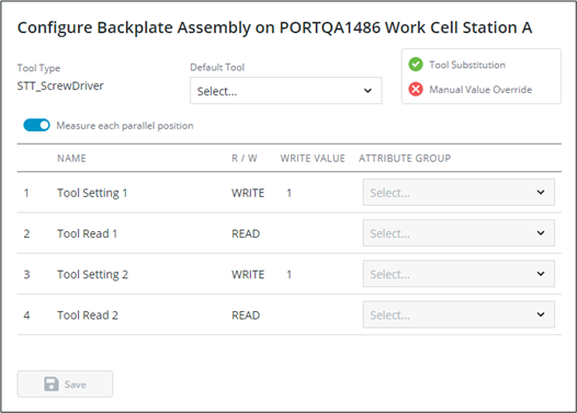
Step Three: Configure Tools
If the route includes smart tool steps on the work instructions, additional configuration is required and Step Three: Configure Tools will be navigable within the route setup process.
The left pane lists all smart tool steps within the route. Selecting a step on the list will load its configuration in the right pane.
All stations under a work cell will need separate configuration. |
To complete configuration for a step not flagged for parallel execution:
1. Select the default tool for the step.
a. The tool type selected during authoring is displayed for reference.
b. The settings for Tool Substitution and Manual Value Override are displayed for reference. A  is shown if allowed,
  if not allowed. When tool substitution is not allowed, the operator must use the default tool.
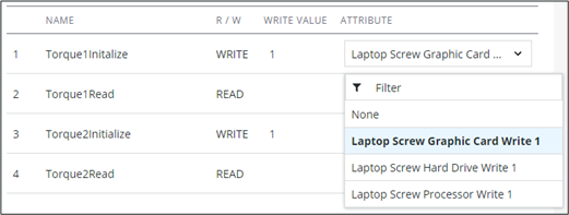
2. Map each read/write item to an attribute for IoT connectivity.
Attribute configuration and IoT tag mapping is handled in the Smart Tool Configuration display. |
a. Select the attribute in the dropdown for each item. Attributes must be unique per read or write action within the sequence number. i.e., a tool cannot read from or write to the same attribute twice within a sequence number.
3. Click Save. If fully configured, the step will be updated with in the left pane.
Configuring a smart tool step on a work instruction flagged for parallel execution is very similar to one that is not flagged, with the following differences:
• The Default Tool dropdown will only show smart tools with enough positions to match the station’s capacity.
• You can toggle Measure each parallel position to configure attribute groups to collect data for each serial number. The tool will read/write to all serial numbers at the same time. If this toggle is selected, the smart tool must also have enough distinct attributes within the attribute groups available to write separate values for each serial number.
◦ This will change the Attribute drop down to an Attribute Group dropdown. Select an attribute group for each sequence item.
• When Measure each parallel position is off, entered data will be saved on the configured attributes. The tool will read/write values for the step.
The top navigation link will change to a green complete state when all smart tool steps are fully configured on the route.
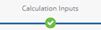
Step Four: Calculation Inputs
If the route includes calculation steps on its work instructions, additional configuration is required and Step Four: Calculation Inputs will be navigable within the route setup process.
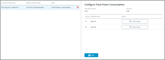
The left pane lists all parts validation steps within the route. Selecting a step on the list will load its configuration in the right pane.
To complete configuration for a parts validation step:
1. Map each input alias to a step within the route:
a. Click Select Input to launch the Select Input pop-up.
b. Select a step within the route in the left list. Calculations can use data collected on any previous step within the route. You can filter steps by work instruction using the filter dropdown.
c. Select an attribute in the right list.
d. Click Confirm.
e. The input will be updated with the work instruction › step › attribute shown inside a tag. Click  to remove the input configuration, or on the name to change it.
2. Click Save. If fully configured, the step will be updated with in the left pane.
The top navigation link will change to a green complete state when all parts validation steps are fully configured on the route.
Step Five: Parts Validation
If your route includes parts validation steps on its work instructions, additional configuration is required and Step Five: Parts Validation will be navigable within the route setup process.
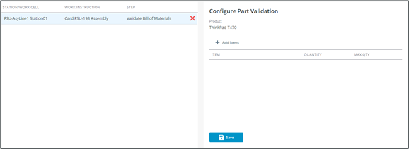
The left pane lists all parts validation steps within the route. Selecting a step on the list will load its configuration in the right pane.
To complete configuration for a parts validation step:
1. Click Add Items to launch the Add Bill of Materials Items pop-up.
2. Select the bill of materials version from the Bill of Materials dropdown. Parts validation steps cannot use more than one bill of materials version. When subsequent parts validation steps are configured on the route, the bill of materials version will be automatically selected.
3. Select one or more bill of materials items from the list.
4. Click Add.
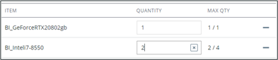
5. Enter a Quantity for each item.
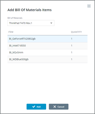
Part quantity for the entire route cannot exceed the bill of material version specifications. A part’s quantity may be split between steps if the total overall does not exceed the bill of materials. This is indicated by the MAX QTY column, where the first number shows the remaining available quantity and the second shows the total quantity specified in the bill of materials. |
6. Click Save. If fully configured, the step will be updated with in the left pane.
The top navigation link will change to a green complete state when all parts validation steps are fully configured on the route.