Working with the ThingView Data Property
You can use the Data property of ThingView widget to perform a cross selection and color highlighting between the 3D model and an external source. To use this Data property along with the Grid widget, perform the following steps.
|
|
Before performing a cross selection, you must know the occurrence ID paths of the 3D model.
|
Creating a Data Shape
Perform the following steps to create a Data Shape with the name SamplePartDataShape:
1. In the Composer, browseto > .
2. Click New to create a new Data Shape.
3. Specify the Name as SamplePartDataShape.
4. Click Save to save the Data Shape.
5. Click Field Definitions to add fields.
6. Click Add. The New Field Definition panel opens.
7. Create a field with the following details:
◦ Name—IDPath
◦ Base Type—STRING
◦ Select the Is Primary Key option.
8. Save the field with the details.
9. Create and save a second field with the following details:
◦ Name—PartName
◦ Base Type—STRING
10. Create and save a third field with the following details:
◦ Name—Stock
◦ Base Type—NUMBER
◦ Select Has Default Value. Specify 0 as the default value.
11. Click Save.
Creating a Thing
Perform the following steps to create a Thing with the name SamplePartThing:
1. In the Composer, browseto > .
2. Click New to create a new Thing.
3. Specify the Name as SamplePartThing.
4. Specify the Base Thing Template as GenericThing.
5. Click Save to save the Thing.
6. Click Services and Add to define a service to get the details of the part in a InfoTable.
7. Specify the following details for the service:
◦ Name—GetPartDetails
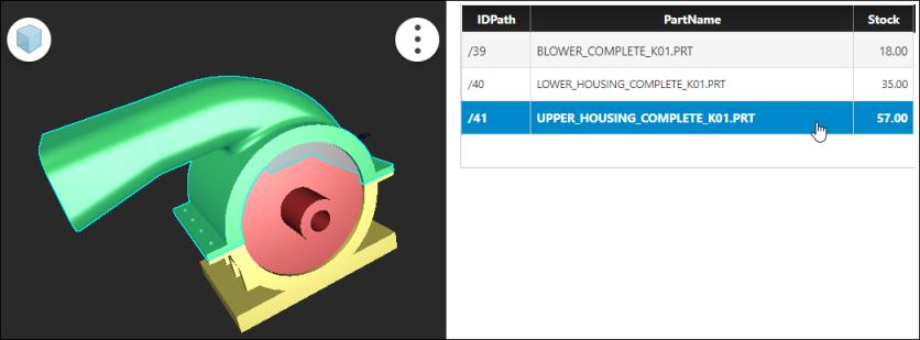
◦ Specify the details of the model you want to add to a Data Table. For example, the following sample code specifies the IDPath, PartName, and Stock details of the model:
var data = [
{
"IDPath": "/39",
"PartName": "BLOWER_COMPLETE_K01.PRT",
"Stock": 18
},
{
"IDPath": "/40",
"PartName": "LOWER_HOUSING_COMPLETE_K01.PRT",
"Stock": 35
},
{
"IDPath": "/41",
"PartName": "UPPER_HOUSING_COMPLETE_K01.PRT",
"Stock": 57
}
];
var result = DataShapes.SamplePartDataShape.CreateValues();
for(var i =0;i<data.length;i++) {
result.AddRow(data[i]);
}
{
"IDPath": "/39",
"PartName": "BLOWER_COMPLETE_K01.PRT",
"Stock": 18
},
{
"IDPath": "/40",
"PartName": "LOWER_HOUSING_COMPLETE_K01.PRT",
"Stock": 35
},
{
"IDPath": "/41",
"PartName": "UPPER_HOUSING_COMPLETE_K01.PRT",
"Stock": 57
}
];
var result = DataShapes.SamplePartDataShape.CreateValues();
for(var i =0;i<data.length;i++) {
result.AddRow(data[i]);
}
◦ Under Output, specify the following details:
▪ Output type—INFOTABLE
▪ Data Shape—SamplePartDataShape
▪ Infotable type—Just Infotable
8. Click Done to save the service.
9. Save the Thing.
Creating Style Definitions
Perform the following steps to create three Style Definitions:
1. In the Composer, browseto > .
2. Click New to create a new Style Definition.
3. Specify the Name as SampleLowStockStyleDefinition.
4. Click Style Information.
5. Select the Text Color as red.
6. Click Save to save the Style Definition.
7. Create the second Style Definition with the name SampleMediumStockStyleDefinition.
8. Select the Text Color as yellow and save the Style Definition.
9. Create the third Style Definition with the name SampleHighStockStyleDefinition.
10. Select the Text Color as green and save the Style Definition.
Creating the State Definition
Perform the following steps to create a State Definition:
1. In the Composer, browseto > .
2. Click New to create a new State Definition.
3. Specify the Name as SampleStockStateDefinition.
4. Click State Information.
5. In the Apply State list, select Numeric.
6. Click Default.
7. Specify the Display Name as DefaultStockDisplay.
8. In Style, search for the State Definition you want set as the default. For this example, search and select SampleHighStockStyleDefinition.
9. Save the state information.
10. Click Add in State Information to add a new state definition.
11. For this example, retain the Operator value as Less than (<).
12. Specify the Value as 20 and Display Name as Low Stock Levels.
13. Search and select SampleLowStockStyleDefinition.
14. Save the state information.
15. Create the second state with Value set as 40 and Display Name as Medium Stock Levels.
16. Search and select SampleMediumStockStyleDefinition.
17. Save the state information.
18. Create the third state with Value set as 100 and Display Name as High Stock Levels.
19. Search and select SampleHighStockStyleDefinition.
20. Save the default state information.
21. Click Save.
Creating the Mashup
Perform the following steps to create a Mashup with the name SamplePartMashup:
1. In the Composer, browseto > .
2. Click New. The New Mashup dialog box opens.
3. Select Static and click OK.
4. Specify the Name as SamplePartMashup.
5. Click Save to save the Mashup.
6. Click Design.
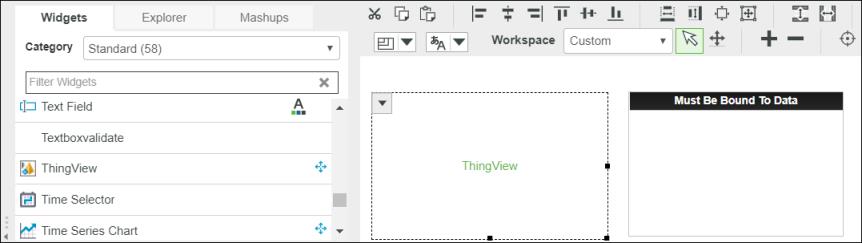
7. From the Widgets pane, drag the ThingView widget to the layout.
8. From the Widgets pane, drag the Grid widget to the layout.
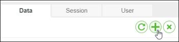
9. In the dock, under Data, click +. The Add Data dialog box opens.
10. In the Select Entity field, search for the Thing you created. In this example, search for SamplePartThing and select it. The services available with the Thing are listed.
11. In the Select Services field, search for the service created in the Thing. In this example, search for GetPartDetails.
12. Click the right pointing arrow in the GetPartDetails service to add it to the Mashup.
13. Click Done.
14. In the dock, expand GetPartDetails.
15. Under Returned Data, click and drag All Data. The parameters available with service are listed.
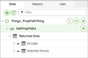
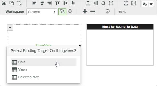
16. Drag the All Data parameter to the ThingView widget. The parameters available with the ThingView widget appears.
17. Select the Data parameter of the ThingView widget. The part data is now bound to the widget.
18. Similarly, under Returned Data, drag the All Data parameter to the Grid widget. Bind it to the data parameter of the Grid.
19. Select the ThingView widget in the layout. The widget borders along with an arrow are shown in the layout area.
20. Place the pointer on the arrow. A list of options available with the ThingView widget appears.
21. Select Configure Bindings. The Configure Widget dialog box appears.
22. Under Events, select Loaded.
23. Click Triggered Services. The Add Services to Trigger from this Event dialog box opens.
24. Select GetPartDetails service.
25. Click Done in all the open dialog boxes.
26. In the ProductToView property, specify the URL of the Creo View structure file.
27. In the OccurrenceField property, select IDPath.
If the fields are not displayed in the property, select the ThingView widget in the Mashup to show the available fields from the data property. |
28. In the DataFormatter property, click State Formatting. The Configure State Formatting dialog box opens.
29. Specify the following details:
◦ Select State-based Formatting option.
◦ In the Dependent Field, select Stock.
◦ In State Definition, select SampleStockStateDefinition.
◦ Click Done to save the State Formatting.
30. Click Save to save the Mashup.
31. Click View Mashup to view the Mashup.
In the Mashup, when you click the part on the model, the corresponding row in the table is automatically selected. Similarly, if you select a part in the row, it is highlighted in the model.