Internal domain diagram (IDL code)

An Internal Domain Diagram allows you to create Nodes in a Domain.
Create an Internal Domain Diagram from a Domain: right-click the Domain, and select > .
All Internal Domain Diagrams are shown in the  DnC Elements pane - expand the Internal Domain Diagram folder.
DnC Elements pane - expand the Internal Domain Diagram folder.An Internal Domain Diagram is based on a UML Composite Structure Diagram.
An Internal Domain Diagram can show the following IDL items.
Domain
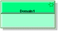
The owning Domain is added to the Internal Domain Diagram on creation.
Note that a Component's view options are set through the Class entry.
Node
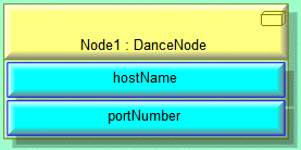
To create a Node: click the  Node button, and then click within the owning Domain.
Node button, and then click within the owning Domain.To add an existing Node: click the Node button, right-click within the owning Domain, and then click the command for the Node you want to add.
Node button, right-click within the owning Domain, and then click the command for the Node you want to add.To populate missing Nodes: right-click the Domain, and select > . Alternatively, you can drag a Node from an appropriate pane to the Domain on the diagram.
For information about specifying the host name and port number of a Node, see
Creating a node.
Note that a Node's view options are set through the Part entry.
The following sections provide information about how an Internal Domain Diagram is used in the model.
Owned By

Creates or shows these items

IDL Profile properties
None.