NSV-7 System quality requirements description (UPDM - NAF aliases)

Creation
To create an NSV-7 System Quality Requirements Description:
• Right-click the
Architectural Description or
Service Description that is to own the NSV-7 System Quality Requirements Description, point to New, point to Matrix/Table, point to NAF, and then click NSV-7 System Quality Requirements Description.
• Right-click the
Capability Configuration,
Organization,
Physical Architecture,
Post,
Resource Artifact,
Responsibility,
Service Access,
Service Description or
Software that is to own the NSV-7 System Quality Requirements Description, point to New, point to NAF, and then click NSV-7 System Quality Requirements Description.
When you open an NSV-7 System Quality Requirements Description, Modeler can generate it as HTML for viewing in your Internet browser, or generate it as a spreadsheet for viewing in Microsoft Excel. To specify how matrices and tables are opened for a model: in the Packages pane, right-click the Model, point to > > , and then select HyperTextMarkupLanguage_HTML or Excel_XLS.
Each time you open an NSV-7 System Quality Requirements Description, Modeler generates the product using the latest data from the model.
Purpose
On an NSV-7 System Quality Requirements Description:
• View measured properties that are available for system resources through Actual Property Set and Service Level Value Set elements.
• For those measured properties, view the permitted minimum and maximum values, and the actual values that have been set through the Actual Property Set and Service Level Value Set elements.
Elements Shown

The NSV-7 System Quality Requirements Description shows the following elements:
• The owner of an NSV-7 System Quality Requirements Description determines which system resource elements are shown in the table:
◦ For an Architectural Description or Service Description owned NSV-7 System Quality Requirements Description, a row is created for each system resource that is found in the analyzed Packages.
◦ For a system resource owned NSV-7 System Quality Requirements Description, a row is created for only the system resource that owns the NSV-7 System Quality Requirements Description.
◦ A system resource can be an
Architectural Description,
Capability Configuration,
Organization,
Physical Architecture,
Post,
Resource Artifact,
Responsibility,
Service Access,
Service Description or
Software element.
The Type and Name (System Resource) columns are populated from the Type and Name properties of each system resource.
• For each system resource row, a sub-row is created for each
Actual Property Set and
Service Level Value Set that is applied to the system resource.
The Name, Intention and Actual Value columns are populated from the Name, Intention and Actual Value properties of each Actual Property Set and Service Level Value Set.
The Unit and Dimension columns are populated from the names of any Unit or Dimension elements that are linked to the type of the Actual Property Set or Service Level Value Set. The type of an Actual Property Set or Service Level Value Set can be linked to a Unit or Dimension only when it is based on a SysML Value Type.
• For each Actual Property Set and Service Level Value Set sub-row, a sub-row is created for each measured property that the Actual Property Set or Service Level Value Set provides.
A measured property can be a
Capability Property,
Condition Property,
Environment Property,
Measurement,
Property, or
Service Attribute. The owning element determines which measured properties are available. For example, you can create only Measurement measured properties for a Measurement Set.
The Property, Minimum Value and Maximum Value columns are populated from the Name, minValue and maxValue properties of each measured property.
Analyzed Packages
For a system resource owned NSV-7 System Quality Requirements Description, the Analyzed Packages are ignored and only the owning system resource appears in the table.
For an Architectural Description or Service Description owned NSV-7 System Quality Requirements Description, by default the NSV-7 System Quality Requirements Description searches for system resource elements that are contained within the Architectural Description or Service Description that owns the NSV-7 System Quality Requirements Description.
To search for system resource elements from other Architectural Description and Service Description packages:
• Right-click the NSV-7 System Quality Requirements Description, point to Links, and then click Analyzed Packages. From the Links Editor, select the Architectural Description and Service Description packages from which you want to search for system resource elements.
Example

In this example:
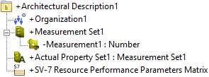
• Architectural Description1 contains NSV-7 System Quality Requirements Description1 and the system resource Organization1.
• We create a Measurement Set named Measurement Set1.
• From Measurement Set1, we create a Measurement named Measurement1. On the Measurement tab of its Property Pages, we set the minValue and maxValue properties of Measurement1 to 0 and 100 respectively.
• We create an Actual Property Set named Actual Property Set1 and select Measurement Set1 as its type.
• We apply Actual Property Set1 to Organization1.
To create this relationship from a system resource: right-click the system resource, point to Links, and then click Actual Property Set.
• Through Actual Property Set1 we set the actual value of Measurement1 to 50.
To set the actual value for an Actual Property Set: right-click the Actual Property Set, point to Set, and then click Values. From the Instance Editor, set the values of the measured properties as required.
When generated, NSV-7 System Quality Requirements Description1 appears as follows.

From the table you can see the following:
• Organization1 has been found in the analyzed Packages.
• Organization1 uses Actual Property Set1 to specify actual values of measured properties provided by Measurement Set1, which in our example is Measurement1.
• The actual value of Measurement1 has been set to 50. The minimum value of Measurement1 is 0 and its maximum value is 100.
The following sections provide information about how an NSV-7 System Quality Requirements Description is used in the model.
Create an NSV-7 System Quality Requirements Description from
Creates or shows these UPDM elements


