Overview of stimuli on sequence diagrams
You can show the following stimuli on a Sequence Diagram:
• Event messages (instances)
• Operation messages (instances)
• Operation replies (instances)
• IO Flows
• Probes
Messages and IO Flows are shown on the diagram as horizontal arrows linking the lifelines of valid objects. Probes are shown as lollipops.
Message passing using Operation calls and Events can be either synchronous or asynchronous.
• Synchronous means that each time a message is sent to an object, control passes from the sending object to the receiving object; on completion of the call control is passed back to the calling object. Operation messages are typically synchronous.
• Asynchronous means that the sending and receiving objects have separate threads of control that do not synchronize during message passing. Event messages are typically asynchronous.
The following table summarizes what object types can be the source (S) and target (T) objects for each stimuli type.
|
Object
|
Operation Message
|
Reply Message
|
Event Message
|
IO Flow
|
Probe
|
|---|---|---|---|---|---|
|
Actor
|
S
|
T
|
S & T
|
-
|
-
|
|
Instance
|
S & T
|
S & T
|
S & T
|
S & T
|
S
|
|
Interface Device
|
-
|
-
|
S & T
|
-
|
-
|
|
Package
|
S & T
|
S & T
|
S & T
|
-
|
S
|
|
Part
|
S & T
|
S & T
|
S & T
|
S & T
|
S
|
|
Port
|
S & T
|
S & T
|
S & T
|
S & T
|
S
|
|
Subsystem
|
-
|
-
|
S & T
|
-
|
-
|
|
System Boundary
|
S
|
T
|
S & T
|
S & T
|
S
|
Event messages (instances)
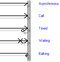
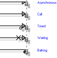
An Event message is a stimulus sent from one object to another. An Event message is shown as a horizontal arrow with a solid line and an open arrow head. Additional notation indicates the timing of the Event.

When you add an Event message to a Sequence Diagram, you are adding an instance of that Event. You can set instance properties for an Event message by right-clicking the message, and then clicking Instance Properties. You can set and display the following instance properties of an Event message on a Sequence Diagram: Actual Parameters and Latency. You can apply Stereotypes to an Event message.
The source object for an Event message can be the System Boundary or any object. The target object can be the System Boundary or any object.
For information about adding Event messages to a Sequence Diagram, see
Adding event messages to a sequence diagram.
Operation messages (instances)
An Operation message shows that an object calls an Operation in the target object. An Operation message is shown as a horizontal arrow with a solid line and solid arrow head. Additional notation indicates the timing of the Operation.

When you add an Operation message to a Sequence Diagram, you are adding an instance of that Operation. You can set instance properties for an Operation message by right-clicking the message, and then clicking Instance Properties. You can set and display the following instance properties of an Operation message on a Sequence Diagram: Actual Parameters, Return Value, Variable Name and Latency. You can apply Stereotypes to an Operation message.
The source object for an Operation message can be the System Boundary, a Package or Actor; or an Instance, Part or Port whose type owns or inherits the Operation. The target object can be a Package, or an Instance, Part or Port whose type owns or inherits the Operation.
Note that an Instance's type can inherit an Operation through a Generalization relationship to another item, and through a bind Dependency relationship to a template item.
For information about adding Operation messages to a Sequence Diagram, see
Adding operation messages to a sequence diagram.
Reply messages (instances)
A Reply message shows that an object's Operation sends a reply to another object. A Reply message is shown as a horizontal arrow with a dashed line and solid arrow head.

When you add a Reply message to a Sequence Diagram, you are adding an instance of that Operation. You can set instance properties for a Reply message by right-clicking the message, and then clicking Instance Properties. You can set and display the following instance properties of a Reply message on a Sequence Diagram: Actual Parameters, Return Value, Variable Name and Latency.
The source object for a Reply message can be a Package, or an Instance, Part or Port whose type owns or inherits the Operation. The target object for a Reply message can be the System Boundary, a Package or Actor; or an Instance, Part or Port whose type owns or inherits the Operation.
Note that an Instance's type can inherit an Operation through a Generalization relationship to another item, and through a bind Dependency relationship to a template item.
For information about adding Reply messages to a Sequence Diagram, see
Adding reply messages to a sequence diagram.
IO Flows
An IO Flow shows that something flows from an object to another object. An IO Flow is shown as a horizontal arrow with a solid line and barbed arrow.

The source object for an IO Flow can be the System Boundary, an Instance, Part or Port. The target object can be the System Boundary, an Instance, Part or Port. The System Boundary cannot be the source and target of an IO Flow.
For information about adding IO Flows to a Sequence Diagram, see
Adding IO flows to a sequence diagram.
Probes
A probe is a stimulus to an included or extended Use Case. A probe is shown as a horizontal lollipop.

The included relationship is used to extract a common course of action. An included Use Case is not aware of what is using it.
An extend relationship models optional parts of Use Cases and provides additional functionality. An extended by Use Case knows how to insert itself into a basic Use Case.
For information about Probes to a Sequence Diagram, see
Adding probes to a sequence diagram.