Overview of adding and moving swimlanes (general flow diagram)
|
|
• This topic applies to General Flow Diagrams.
• In Studio 7.0 and earlier versions, General Flow Diagrams were named Activity Diagrams: If you created Activity Diagrams in Studio version 7.0 or earlier and have upgraded, your Activity Diagrams are now called General Flow Diagrams in Modeler.
• Studio 7.1 included new Activity Diagrams, which you should use in preference to General Flow Diagrams. General Flow Diagrams are being deprecated and are included in Modeler only for backward compatibility.
• Should you need to create General Flow Diagrams, they can now be created only from the Model or a Package. After creating a General Flow Diagram you can drag it to an Activity, Actor, Class, Data Type, Event, Interface, Operation, Subsystem or Use Case.
|
You can add Swimlanes to a General Flow Diagram as top level Swimlanes or nested Swimlanes through the  Swimlane button on the General Flow Diagram tab.
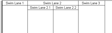
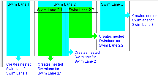
Swimlane button on the General Flow Diagram tab.In the following example, Swim Lane 1, Swim Lane 2 and Swim Lane 3 are top level Swimlanes. Swim Lane 2 has two nested Swimlanes named Swim Lane 2.1 and Swim Lane 2.2.
After adding Swimlanes to a General Flow Diagram, you can move them to alternative positions or change their nesting by dragging the Swimlane (through its name) to a different location.
If you create a nested Swimlane for a Swimlane that contains items but no nested Swimlanes, Modeler creates a nested Swimlane of the same name to own the contained items.
|
|
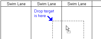
When you drag a Swimlane to a different position, the top left corner of the Swimlane outline determines the drop target, as shown here.
 |
Creating Top level swimlanes
To create a top level Swimlane, click the Swimlane button, and then click the boundary of a top level Swimlane. The boundary you click determines where the Swimlane is created.
Swimlane button, and then click the boundary of a top level Swimlane. The boundary you click determines where the Swimlane is created.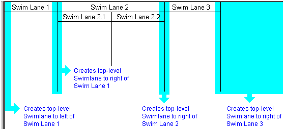
Creating nested swimlanes
To create a nested Swimlane, click the Swimlane button, and then click the Name of the Swimlane that is to nest the Swimlane you are creating.
Swimlane button, and then click the Name of the Swimlane that is to nest the Swimlane you are creating.|
|
When you are adding a nested Swimlane, a ToolTip displays the name of the Swimlane that will nest the Swimlane you are creating.
|
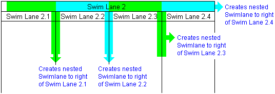
If there are existing nested Swimlanes, where you click determines where the nested Swimlane is positioned (you can click internal boundaries of nested Swimlanes).
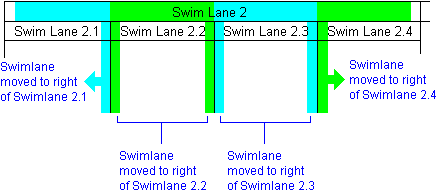
Moving a swimlane to a top level position
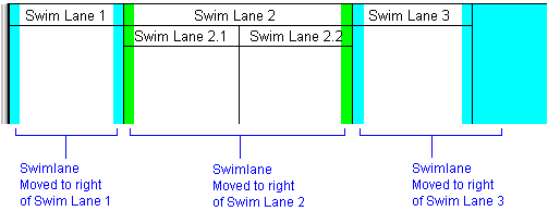
To move a Swimlane to a top level position, drag the Swimlane (through its name) to the boundary of a top level Swimlane.
|
|
The top left corner of the Swimlane outline determines the drop target.
|
If you want to move a Swimlane to the left most position, move the Swimlane to the right of the left most Swimlane, and then move the left most Swimlane to a different position.
Moving a swimlane to a nested position
To move a Swimlane to a nested position, drag the Name of the Swimlane you want to move, and then drop the left corner of the Swimlane outline on to the Name of the Swimlane that is to nest the Swimlane you are moving.
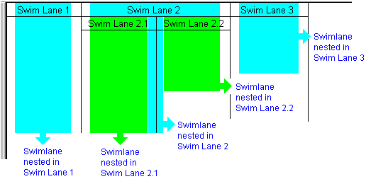
If there are existing nested Swimlanes, where you drop the Swimlane determines where that Swimlane is positioned (you can click on internal boundaries of nested Swimlanes).