Parts
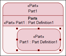
A Part represents a modular unit of a structure such as a system, system component or an external entity that may or may directly interact with the system. Parts can have features such as properties, ports, connectors. Parts can also inherit features and can be decomposed (nested) in sub-parts which are called as its owned members. The following image is an example of a Part with owned members and decomposed Parts.
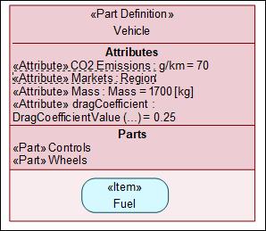
Creating a Part
To create a Part from the System Structure toolbar:
1. On the System Structure Diagram toolbar, click the Part  button.
 button.
2. Click on the diagram. This creates an instance of a Part.
To create a Part from the context menu:
• On the Package browser, right-click on the Package / Library Package in which you want to create the Part, and select > > > . This creates a Part within the selected Package.
Parts Decomposition
In SysML 2.0, with decomposition, you can decompose systems into subsystems and components. Within a diagram, parts and other elements can have owned members that allow system decomposition. Most element types can own most other element types; SysML 2.0 does not have any such restrictions, which gives you the flexibility; however, it depends on you to define your models correctly. The following image is an example of decomposition:
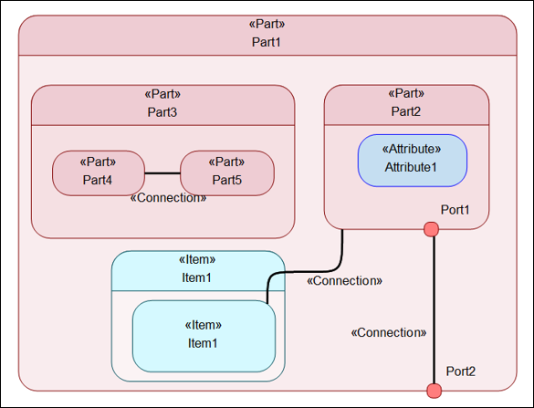
You can create parts or other elements inside parent elements in the diagram using the toolbar. You can also use drag and drop or copy / paste items in the Package browser to break down systems into subsystems. Consider the following example:
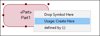
1. On the System Structure Diagram, drag a Part Definition element from the Package Browser and drop it on to a Part Usage item on the diagram. (You can also drop the Part Definition element on the Part Usage element in the Package Browser).

2. A popup dialog is displayed. Select Usage: Create Here.
3. A popup is displayed prompting you to enter a name for the newly created Usage item.
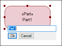
The Parts Usage item is displayed as shown in the image below.
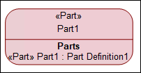
4. On the diagram, right-click the Part and select > . The Populate Nodes dialog opens. Select the nodes that you want to populate and click OK. The newly created Part Usage from the Part Definition is shown in the diagram.
