Overview of sequence diagrams
A Sequence Diagram (OSD) describes a Class, Data Type, Interface, Event, Operation or Use Case through statements and the interaction of objects.
When you open a new Sequence Diagram, the name of the parent item (if there is one) is displayed in the top left corner, and two bars are shown - the System Boundary and Architecture Boundary. You can drag the System Boundary and Architecture Boundary bars to new positions.
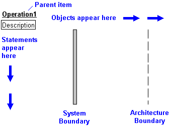
A Sequence Diagram can show the following items:
• Statements—below the Description heading on the left side of the diagram.
• Objects—along the top of the diagram. Each object has a vertical lifeline that extends down from the object.
• Stimuli—between the object lifelines.
• Timing Constraints—between statements.
• interaction frames—for statements.
In addition, you can use the diagram View Options to show or hide Construct Balancing and Line Numbers.
Statements
Statements provide a structured description of the parent Use Case, Event or Operation. Each Statement has a type that specifies its purpose within the structure, such as a sequence, selection or iteration statement. Statements use rich text so that you can include model object references.
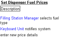
For more information about Statements, click here.
Objects
You can show the interaction of the following objects on a Sequence Diagram: Actors, Instances, Parts, Ports, Interface Devices, Packages and Subsystems. Each object has a lifeline to which Stimuli can link be added. An object can reference a Sequence Diagram or General Flow Diagram to show part decomposition.

You add Parts and Ports by dragging them from an appropriate pane. Use the Parts pane to view Parts and Ports in context. |
For more information about objects on Sequence Diagrams, click here.
Stimuli
You can show the following stimuli on a Sequence Diagram: Event messages (instances), Operation messages (instances), Replies (instances), IO Flows and Use Case probes. Where instances are shown, you can show instance properties on the diagram.

For more information about stimuli on Sequence Diagrams, click here.
Timing Constraints
You can add Timing Constraints to a Sequence Diagram. A Timing Constraint specifies a timing constraint between two Statements. You can link a Timing Constraint to a Constraint item, in which case the Name and Worst Acceptable properties of the linked Constraint are displayed on the diagram. If there is not a linked Constraint, the Caption and Time properties of the Timing Constraint are displayed on the diagram. You can show or hide all Timing Constraints through the Show Timing Constraints check box on the diagram view options.
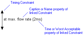
For more information about Timing Constraints, click here.
Interaction Frames
You can add Interaction Frames to Statements for two purposes:
• To provide visual grouping of stimuli - the height of an Interaction Frame is determined by the Statement and its sub-Statements. Sub-constructs are divided by a dashed line in the Interaction Frame.
• To reference a Sequence Diagram or General Flow Diagram - showing interaction occurrences. When an Interaction Frame references a diagram, the Interaction Frame displays 'ref' in the top left corner and the name of the referenced diagram.
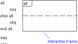
For more information about using Interaction Frames, click here.
Construct Balancing
Construct Balancing helps you see the structure of statements by indicating the start and finish of selection, iteration and parallel structures. You can show or hide construct balancing through the Show Construct Balancing on PDL Statements check box on the diagram view options.
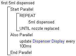
For more information about showing construct balancing, click here.
Line Numbers
Line numbers can help you identify individual statements. You can show or hide line numbers through the Show Line Numbers With PDL Statements check box on the diagram view options.

For more information about showing line numbers, click here.