S7-200 Addressing
S7-200 Addressing
The S7-200 addressing format is the same as the S7-200 PPM addressing format. The model selection in this case determines whether the driver is using PPI protocol (normal S7-200 Mode) or PPM (S7-200 in Point to Point Modem) mode. In both cases, the addressing is the same.
The default data types for dynamically defined tags are shown in bold.
|
Address Type
|
Range
|
Type
|
Access
|
|---|---|---|---|
|
Discrete Inputs
|
I00000-I65535
I00000-I65534
I00000-I65532
I00000.bb-I65535.bb
I00000.bb-I65534.bb
I00000.bb-I65532.bb
|
Byte
Word, Short
DWord, Long, Float
Byte
Boolean, Word, Short
DWord, Long
|
Read / Write
|
|
Discrete Outputs
|
Q00000-Q65535
Q00000-Q65534
Q00000-Q65532
Q00000.bb-Q65535.bb
Q00000.bb-Q65534.bb
Q00000.bb-Q65532.bb
|
Byte
Word, Short
DWord, Long, Float
Byte
Boolean, Word, Short
DWord, Long
|
Read / Write
|
|
Internal Memory
|
M00000-M65535
M00000-M65534
M00000-M65532
M00000.bb-M65535.bb
M00000.bb-M65534.bb
M00000.bb-M65532.bb
|
Byte
Word, Short
DWord, Long, Float
Byte
Boolean, Word, Short
DWord, Long
|
Read / Write
|
|
Special Memory
|
SM00000-SM65535
SM00000-SM65534
SM00000-SM65532
SM00000.bb-SM65535.bb
SM00000.bb-SM65534.bb
SM00000.bb-SM65532.bb
|
Byte
Word, Short
DWord, Long, Float
Byte
Boolean, Word, Short
DWord, Long
|
Read / WriteSM0-SM29 are Read Only
|
|
Variable Memory
|
V00000-V65535
V00000-V65534
V00000-V65532
V00000.bb-V65535.bb
V00000.bb-V65534.bb
V00000.bb-V65532.bb
|
Byte
Word, Short
DWord, Long, Float, String
Byte
Boolean, Word, Short
DWord, Long, String
|
Read / Write
|
|
Timer Current Values
|
T00000-T65535
|
DWord, Long
|
Read / Write
|
|
Timer Status Bits
|
T00000-T65535
|
Boolean*
|
Read Only
|
|
Counter Current Values
|
C00000-C65535
|
Word, Short
|
Read / Write
|
|
Counter Status Bits
|
C00000-C65535
|
Boolean*
|
Read Only
|
|
High Speed Counters
|
HC00000-HC65535
|
DWord, Long
|
Read Only
|
|
Analog Inputs
|
AI00000-AI65534**
|
Word, Short
|
Read Only
|
|
Analog Outputs
|
AQ00000-AQ65534**
|
Word, Short
|
Write Only
|
*For Timer and Counter status bits, dot bit notation is not used. The status bit for timer 7 would be T7 declared as Boolean.
**For Analog Inputs and Outputs, the address must be even (AI0, AI2, AI4...). Analog Outputs (AQ) are Write Only: there is no method for reading the value of Analog Outputs from the device. Write-only data types of this driver return the last value written when read if an initial write to device has completed. If an initial write has not completed, the driver returns a value of 0 when read. This only applies while a client is connected to the server.
The actual number of addresses of each type depends on the Siemens S7-200 device in use. Each type does not necessarily support an address of 0 to 65535. For address ranges, refer to the device's documentation.
Optional Dot Bits
For Byte, Word, Short, DWord or Long data types, an optional .bb (dot bit) can be appended to the address to reference a bit in a particular value. The valid ranges for the optional bit is 0-7 for Byte types; 0-15 for Word, Short, and Boolean types; 0-31 for DWord and Long types; and 1-211 for String types. Float types do not support bit operations. Boolean and String types require a bit number. The bit number for String types specifies the number of characters in the string.
Dynamic addresses with bit numbers in the range of 0-7 default to Byte; 8-15 default to Word; 16-31 defaults to DWord. V Memory addresses with a bit number larger than 31 defaults to String. The following diagram illustrates how the driver maps bits within the controller.
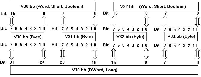
 Note: V30.10@bool, V30.2@byte, and V30.26@DWord all reference the same bit in the controller.
Arrays
Certain memory types (I, Q, M, SM, V, AI, and AQ) support an array operation. Boolean arrays are not allowed at this time. To specify an array address, append [rows][cols] to the end of an address. If only [cols] is specified, [rows] defaults to 1. With the array type, it is possible to read and write a block of 200 bytes at one time.
The maximum array size for Word and Short types is 100, and for DWord, Long and Float types is 50. The array size is determined by the multiplication of rows and cols.
Note: The maximum array size also depends on the maximum block size of the device being used.Examples
1. To read and write an array of 10 Variable Memory Float values starting with V10, declare an address as follows: V10 [1][10]. Choose Float for the data type.
Note: This array reads and writes values to registers V10, V14, V18, V22 ... V46.2. To read and write to bit 23 of Internal Memory Long M20, declare an address as follows: M20.23. Choose Long for the data type.
Strings
The driver allows for variable length strings to be stored in Variable Memory locations. The bit number specifies the string length (1-211) in characters. String data that is sent to the device, but is smaller in length than the string character count (bit number), is null terminated. String data that meets or exceeds the character length is truncated to the character count and sent to the device without a null terminator.
To read and write a string starting at V5 for a length of 10 characters, declare an address as follows: V5.10. Choose string for the data type.
Notes:1. V Memory locations V5-V14 would be used to store this 10 character string.
2. Not all devices support up to 211 character requests in a single transaction. To determine the maximum number of characters that can be requested in a transaction, consult the device's documentation. This value is the largest string the driver can Read/Write to and from the device.
 Caution: When modifying Word, Short, DWord, Long and Float types remember that each address starts at a byte offset within the device. Therefore, Words V0 and V1 overlap at byte 1. Writing to V0 modifies the value held in V1. Similarly, DWord, Long, and Float types can also overlap. It is recommended that these memory types be used so that overlapping does not occur. As an example, when using DWords, use V0, V4, V8, and so on to prevent overlapping bytes.