E5AX-A Address Description
E5AX-A Address Description
The default data types are shown in bold.
|
Mnemonic
|
Description
|
Data Type
|
Access
|
|---|---|---|---|
|
AL-1
|
Alarm 1 set temperature
(-999-9999 deg TC)*(-99.9-999.9 deg Pt)
|
Float, DWord, Long
|
Read/Write
|
|
AL-1-MD
|
Alarm 1 mode of operation*
(0-9)
|
Short, Word
|
Read Only
|
|
AL-1-OUT
|
Alarm 1 output status
TRUE = alarm on
FALSE = alarm off
|
Bool
|
Read Only
|
|
AL-2
|
Alarm 2 set temperature
(-999-9999 deg TC)
(-99.9-999.9 deg Pt)
|
Float, DWord, Long
|
Read/Write
|
|
AL-2-MD
|
Alarm 2 mode of operation*
(0-9)
|
Short, Word
|
Read Only
|
|
AL-2-OUT
|
Alarm 2 output status
TRUE = alarm on
FALSE = alarm off
|
Bool
|
Read Only
|
|
AT
|
Auto tuning in progress
Write TRUE to start AT
Write FALSE to stop AT
AT remains TRUE until the device completes the auto tuning procedure (or the user terminates it).
Driver does not accept any write commands other than AT=FALSE during auto tuning.
|
Bool
|
Read/Write
|
|
BACKUP
|
Backup RAM to non-volatile memory
Write: Anything to initiate backup procedure
Read:
TRUE = non-volatile memory is not current
FALSE = non-volatile memory is current  Note: Device is unresponsive for approximately 500 ms during backup. Note: Device is unresponsive for approximately 500 ms during backup. |
Bool
|
Read/Write
|
|
BURNOUT
|
Heater burnout detected
TRUE = heater burnout detected
FALSE = heater OK
|
Bool
|
Read Only
|
|
CTR-MD
|
Control mode of operation*
TRUE = "On/Off"
FALSE = "2-degree of freedom PID"
|
Bool
|
Read Only
|
|
D
|
Rate time set value
(0-3999 s)
|
Short, Word
|
Read/Write
|
|
DSPL-UNIT
|
Display unit*
TRUE = degrees F
FALSE = degrees C
|
Bool
|
Read Only
|
|
I
|
Reset time set value
(0-3999 s)
|
Short, Word
|
Read/Write
|
|
IN-S
|
Input shift set value
(-999-9999 deg TC)
(-99.9-999.9 deg Pt)
|
Float, DWord, Long
|
Read/Write
|
|
IN-S_DSPL
|
Input shift display enable*
TRUE = enabled
FALSE = disabled
|
Bool
|
Read Only
|
|
IN-T
|
Input (sensor) type*
(0-9)
|
Short, Word
|
Read Only
|
|
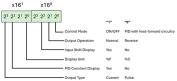
INITIALSTATUS
|
Initial Status tag
For information on the INITIALSTATUS value, refer to the image below. Note: The INITIALSTATUS value is read during initial device setup communications and when reading the following addresses: AL-1-MD AL-2-MD CTR-MD DSPL-UNIT IN-S_DSPL IN-T O-TYPE O-OP PID-DSPL |
Short, Word
|
Read Only
|
|
O
|
Output value
(0.0-100.0%)
|
Float, DWord, Long
|
Read Only
|
|
O-TYPE
|
Output type*
TRUE = current
FALSE = pulse
|
Bool
|
Read Only
|
|
O-OP
|
Output mode of operation*
TRUE = normal (cooling)
FALSE = reverse (heating)
|
Bool
|
Read Only
|
|
P
|
Proportional band set value
(0.0-999.9 deg)
|
Float, DWord, Long
|
Read/Write
|
|
PID-DSPL
|
PID display enable*
TRUE = enabled
FALSE = disabled
|
Bool
|
Read Only
|
|
PV
|
Process value (measured temperature)
(-999-9999 deg TC)
(-99.9-999.9 deg Pt) Note: Since hardware status information is passed back to the driver with the PV value, it is important that this memory location be monitored. If a hardware failure should occur (device failure, heater burnout, sensor failure), it is detected and reported by the driver only during a PV read operation. |
Float, DWord, Long
|
Read Only
|
|
RAM-MD
|
RAM mode enable
TRUE = RAM mode
FALSE = backup mode
The driver automatically forces the device into RAM mode to prevent wear on non-volatile memory. Users may backup the contents of RAM by issuing a BACKUP command. Note: If "Remote Mode"is not selected on the device's front panel, the driver cannot automatically force the device into RAM mode. The RMT button and RMT status indicator are located on the front panel. |
Bool
|
Read Only
|
|
REMOTE
|
Remote Mode enable
TRUE = device in Remote Mode
FALSE = device in Local Mode
The driver is not able to write to the device unless Remote Mode is selected on the device front panel.
|
Bool
|
Read Only
|
|
SL-H
|
Set point limit (high)**
|
Float, DWord, Long
|
Read Only
|
|
SL-L
|
Set point limit (low)**
|
Float, DWord, Long
|
Read Only
|
|
SP-S-IN
|
Set point shift input state
TRUE = shift enabled
FALSE = shift disabled
State is forced TRUE by shorting appropriate terminals on device.
|
Bool
|
Read Only
|
|
SV
|
Set value temperature
Setting range: SL-L-SL-H
|
Float, DWord, Long
|
Read/Write
|
|
ADCERR
|
A/D Converter Error/Failure
|
Boolean
|
Read Only
|
|
SENSERR
|
Abnormal Input/Sensor Error
|
Boolean
|
Read Only
|
|
RAMERR
|
RAM Data Error
|
Boolean
|
Read Only
|
*This is a hardware setting. For more information, refer to the device's help documentation.
**This value must be set on device front panel. For information on the valid ranges, refer to the device's help documentation.
Note: TC denotes temperature range for thermocouple sensor types. Pt denotes temperature range for platinum resistance thermometer sensor types. All stated temperature ranges are numerically equal for degrees F and C.INITIALSTATUS Value Format