QJ71C24N Configuration
QJ71C24N Configuration
Provided for reference only. Please refer to the manufacturer documentation.
The QJ71C24N communications module is configured with the GX Developer programming software, which is available from Mitsubishi PLC dealers.
1. To begin configuring the PLC to work with this driver, open an existing GX Developer project. Alternatively, read the current PLC Parameter configuration from the device.
2. Next, edit the PLC Parameter settings.

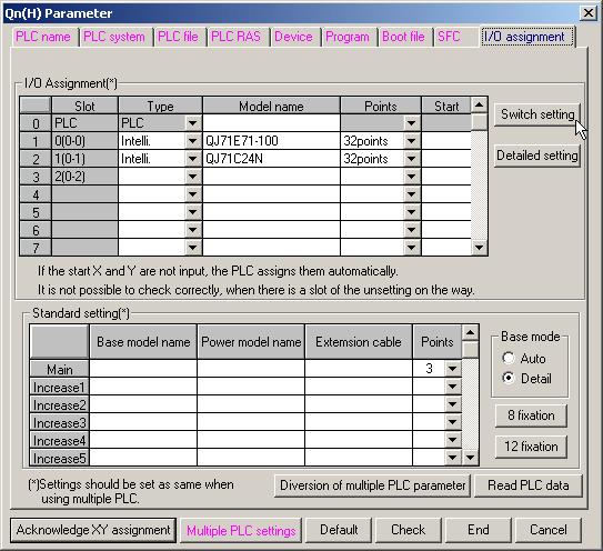
3. Open the I/O Assignment tab and then click Switch Setting to configure the QJ71C24N module. In the example shown below, the PLC has a QJ71E71-100 Ethernet communications module in slot 0 and a QJ71C24N serial communications module in slot 1.
 Note: The recommended software switch settings are shown below.
4. Entries for switch settings can be calculated from the following tables. Switches 1 and 2 are for channel 1 and switches 3 and 4 are for channel 2. For more information, refer to the tables and examples below.
Switch 1/ Switch 3 Transmission Setting
Bit | Description | OFF (0) | ON (1) | Remark |
|---|---|---|---|---|
0 | Operational | Independent | Link | Must be OFF on channel 1 |
1 | Data bits | 7 | 8 | |
2 | Parity bit | No | Yes | |
3 | Even/Odd Parity | Odd | Even | |
4 | Stop bit | 1 | 2 | |
5 | Check Sum | No | Yes | Must be ON for use with this driver |
6 | Write during RUN | Prohibited | Allowed | ON to write data externally |
7 | Setting modifications | Prohibited | Allowed |
Note: To use this driver with its default communications settings (8 data bits, odd parity, 1 stop bit, check sum) and to allow writes during RUN and setting modification, set bits 0 through 7 to 01100111 (0xE6).Switch 1/ Switch 3 Communications Setting
Baud | Bits 8 to 15 |
|---|---|
300 | 0x00 |
600 | 0x01 |
1200 | 0x02 |
0x03 | 2400 |
0x04 | 4800 |
9600 | 0x05 |
14400 | 0x06 |
19200 | 0x07 |
28800 | 0x08 |
38400 | 0x09 |
57600 | 0x0A |
115200 | 0x0B |
Note: To use this driver with its default baud rate of 19200, set bits 8 through 15 to 0x07.Switch 2/ Switch 4 Protocol Setting
Setting | Description |
0x00 | GX Developer |
0x01 | Mode 1* |
0x02 | Mode 2 |
0x03 | Mode 3 |
0x04 | Mode 4 |
0x05 | Mode 5** |
0x06 | Non-procedure |
0x07 | Bidirectional |
0x08 | For linked operation |
0x09 - 0x0D | Prohibited |
0x0E | ROM/RAM/switch test |
0x0F | Loop back test |
*Must be used with A Series driver model.
**Must be used with Q Series driver model.
Note: To use this driver with the Q Series model selected, set switch 2 (or 4) to 0x05. This driver can also be used with the A Series model selected if switch 2 (or 4) is set to 0x01.Switch 5 Channel Setting
Set communication objects as channels between 0 and 31 when multi-drop connection is selected. Set to 0 if 1:1 connection is selected.
Note: Set switch 5 to 0x0000 to assign the station number 0 to the PLC.5. Once the switch settings are entered, write the PLC Parameters back to the device.
6. Then, cycle the power on the PLC to make the new settings active.