Plane Projection
The plane projection

tool (
Projection from one plane to another one) allows you to drag selected elements onto another perspective plane.
This function allows you to use existing parts in another perspective. This can be useful, for example, if you want to change a technical view into a perspective view. Furthermore, you can project elements from one perspective into another.
Perspective Planes
A perspective plane is an area of any orientation which is located in free space. It is obtained when, for example, you move a rectangle into a perspective orientation using transformations such as moving, rotation, reflection and distortion.
Unlike 3D programs, Arbortext IsoDraw does not require you to perform calculations and the like in order to locate a plane. In Arbortext IsoDraw CADprocess you define a plane with the ellipse. Every ellipse can define the plane it is located in by means of the ellipse value and orientation angle.
| A thread also contains all the information relating to the plane it is located in. The term ellipse will be used in the following sections, even if the statements are also valid for threads. |
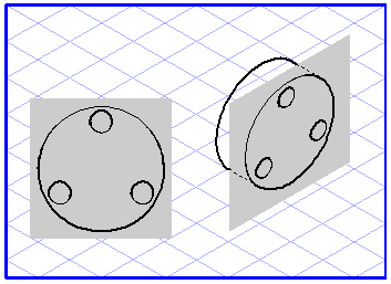
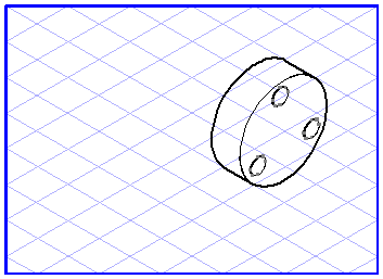
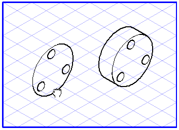
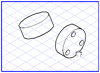
When using the plane projection
tool, it is important you are able to see the planes you are working with. The left-hand illustration shows you a plane in a flat view which is to be projected into a perspective plane. The right-hand illustration shows two planes between which elements can be projected.
Starting and Target Planes
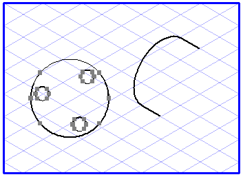
If you want to drag elements from one plane to another, Arbortext IsoDraw needs to know the planes involved. The starting plane defines the plane the elements are located in, while the target plane defines the plane which the elements are to be projected into. Both planes are defined by ellipses:
The starting plane is defined by the ellipse you click with the cursor in order to drag all the selected elements into the new plane. If you click a different element instead, the starting plane will be assumed to be a flat view.
The target plane is defined by the ellipse you touch with the cursor while you are dragging the selected elements over the drawing. If you release the mouse button while this ellipse is selected, the elements will be dragged into this plane. If there is no ellipse due to the fact that you have released the mouse button over an empty part of the drawing, Arbortext IsoDraw assumes that you want to drag all the selected elements from a plane into a flat view.
Three different projections result:
• If only the target plane exists, the elements are dragged from a flat view into a plane.
• If only the starting plane exists, the elements are dragged from a plane into a flat view.
• If both the starting plane and target plane exist, the elements are dragged from one plane to a new one.
| If the Arrow tool is activated, you can switch to the plane projection tool by pressing the CTRL key. You can release the CTRL key again as soon as you have started dragging. |
Projection from a View into a Plane
Select the elements you want to drag into the plane. Select the plane projection
tool. The cursor becomes a move hand

.
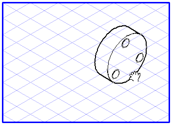
Now click one of the selected elements and drag it over the drawing area. The move hand becomes a fist

. Each ellipse you touch with the cursor during the dragging operation will be selected. If you release the mouse button while an ellipse is selected, all the dragged elements will be projected into this plane.
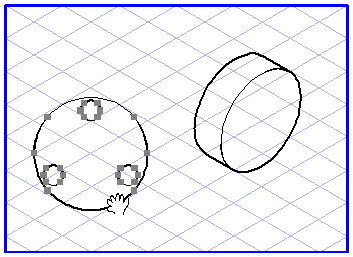
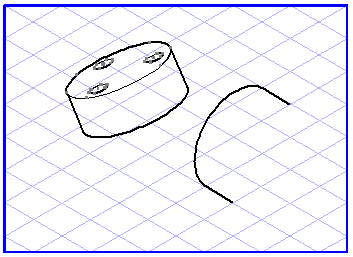
Projection from a Plane into a View
Select the elements you want to drag into a view. Select the plane projection
tool. The cursor becomes a move hand
.
Now click one of the selected ellipses and drag it to an empty space on the drawing area. The move hand becomes a fist
. As soon as you release the mouse button, the dragged elements will be projected out of their current plane into a flat view.
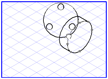
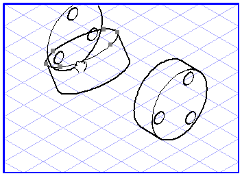
Projection from One Plane into Another
Select the elements you want to drag from one plane into another. Select the plane projection
tool (
Projection from one plane to another one). The cursor becomes a move hand
.
Now click one of the selected ellipses and drag it over the drawing area. The move hand becomes a fist
. Each ellipse you touch with the cursor during the dragging operation will be selected. If you release the mouse button while an ellipse is selected, all the dragged elements will be projected out of their current plane into the target plane.
A Few Tips
The plane projection
tool can greatly simplify the task of working with perspectives. For example, it is often easier to perform changes in a flat view rather than in perspective. Do so by dragging the elements out of their perspective plane into a flat view. Augment or edit them here and then drag them back to the starting plane.
If you move elements back and forth between two planes, they may often not be positioned at the correct angle on the target plane. You should then use the
Perspective rotation
tool to move the elements to the required orientation.
If you hold down the ALT key while dragging the elements, the latter will be scaled so that the diameter of the starting ellipse corresponds to that of the target ellipse.