Penetrating a Cylinder
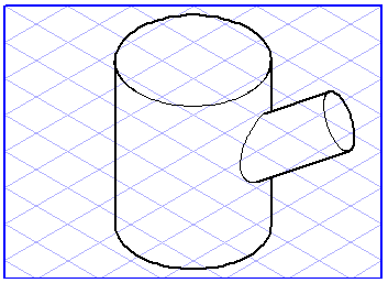
This tool lets you create penetration curves on a cylinder. All elements plane may be used for the cylinder's penetration. This is an easy way to depict branch T’s, for example.
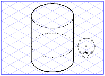
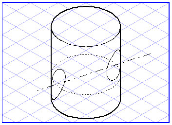
Select the elements which are to penetrate the cylinder. Select the
Penetration through a cylinder
tool from the toolbox. The cursor becomes a move hand

.
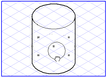
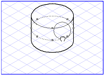
Now click one of the selected elements and drag it over the drawing area. The move hand becomes a fist

. Each ellipse you touch with the cursor during the dragging operation will be selected. If you release the mouse button while an ellipse is selected, all the dragged elements will be imaged onto this cylinder to represent the edges of the penetration curves.
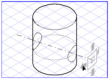
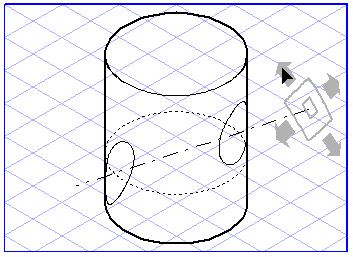
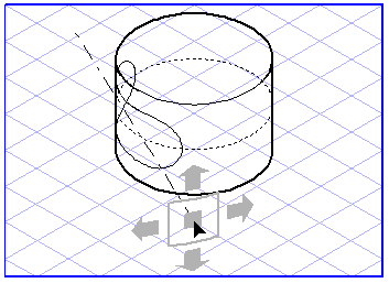
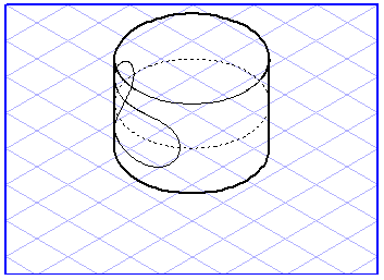
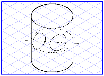
The elements’ penetration curves have not yet been defined finally, you still have the opportunity to change the position of the elements. Four arrows and two rectangles now appear on the illustration. The horizontal arrows let you change the elements' positions in the ellipse plane. Do this by clicking one of the arrows and moving the mouse. You will now see the penetration curves on the cylinder being rotated.
The vertical arrows allow you to change the penetration direction relative to the cylinder. Do this by clicking one of the arrows and moving the mouse. You will see how the central axis of the elements is rotated and the penetration curves move up or down.
It is still possible to change the horizontal position. Do this by clicking the small rectangle and moving the mouse. You will see how the central axis of the elements with the penetration curves is moved outwards away from the center of the cylinder.
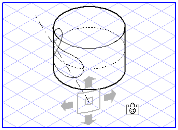
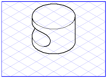
Once you have found a suitable position, move the mouse outside the range of the arrows or the small rectangle.
The cursor becomes a camera

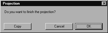
. Click an empty part of the drawing area. The following dialog box appears:
Clicking Cancel lets you quit this dialog box and continue editing the penetration. Clicking OK terminates penetration generation. The final penetration curves are then created. If you click Copy instead, however, all the elements will be copied and the penetration curves created.
The dialog box then closes and you can set about generating another penetration.
Entering Values
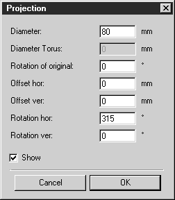
You can control the penetration using either the mouse or keyed-in values. When you see the arrows, hold down the SHIFT key and click the drawing area. The following dialog box appears:
You can change various values in this window. If the Show box is checked, each change will be applied immediately so that you can check the effect of the change.
The diameter corresponds to the diameter of the ellipse which represents the cylinder. The rotation of the original results in all the elements firstly being rotated. If you enter a horizontal offset (Offset hor), the elements are moved horizontally in the ellipse plane. If you enter a vertical offset (Offset ver), the elements are moved either upwards or downwards. The horizontal rotation (Rotation hor) specifies the number of degrees by which the elements have been rotated in the ellipse plane. Vertical rotation (Rotation ver) specifies the number of degrees by which the penetration axis has been rotated out of the ellipse plane.
Clicking OK applies the new values. Click Cancel if you wish to use the settings which were in use before the dialog box was opened.
In the example below, the following values have been entered:
Diameter: | 100 mm |
Rotation of original: | 0 ° |
Offset hor: | -10 mm |
Offset ver: | 0 mm |
Rotation hor: | 300° |
Rotation ver: | 30° |