Generate Callouts for Objects
|
|
The Generate callouts for objects command described below cannot be selected when you are working in 3D mode. After the projection you can select the command in the Objects window and create callouts for the generated 2D illustration.
|
(2D mode only) Use this command to automatically create callouts for the current file. The setting options allow you to control:
• Which objects or groups should receive a callout.
• Where the object information that is used to create callouts comes from; objects in the illustration, a parts list, or a bill of material (BOM).
The callout style and arrangement of the callouts on the drawing can be set as required.
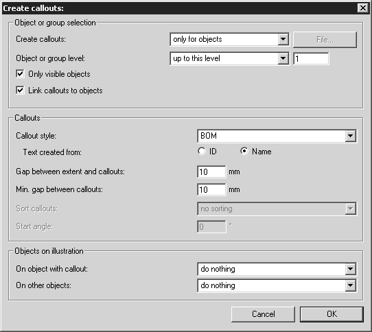
If you select this command, the following dialog box will appear:
Object or Group Selection
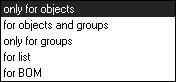
With Create callouts, you can define whether objects and/or groups should receive a callout. Make this selection in the pop-up menu.
If your drawing contains only objects, select only for objects.
If unnamed groups also appear in the Objects window with the name Group and you also want to assign callouts to these groups, select option for objects and groups. If your drawing consists only of groups, select option only for groups. This applies to older Arbortext IsoDraw drawings, for example, or imported drawings without object info. Please ensure that all components and/or units that are to receive a callout are grouped.
If for list is set, the Arbortext IsoDraw file must contain objects. Information about which objects are to receive a callout is obtained from a previously exported object list of the current file. The list can be edited here before use.
An object list of this type is exported as a tab-delimited file. It must contain the IDs or names of the objects. If you want to add a customized positioning to the list, you should export attribute
Name so that the objects can be easily identified. How to create an object list is described in
Preferences.
To define a positioning for the objects, or to remove objects from the list, open the list in a suitable program e.g. Microsoft Excel. The selected attributes for the list appear in columns in the file.
When particular objects are to receive no callout, delete the whole row of entries for the object from the list.
If you want a customized positioning, enter the numbering in a free column. You can select any entries for the numbering. The only important thing is to ensure that the pattern matches the callout style that has been set. If the pattern
Numerical is set, your entries must not contain any letters (see
Show Attribute Window).
Saving the list after editing.
When you select for list, the File button is enabled. Click on this button and search for the appropriate object list in the following dialog box. Confirm your selection by clicking Open.
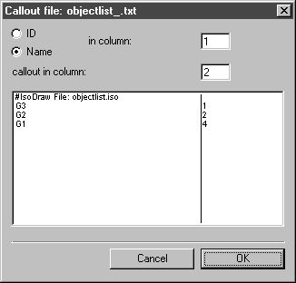
The following dialog box appears:
Here you can select the columns in the object list in which the IDs/names or the callout numbering are entered. Click OK to confirm your selection. Arbortext IsoDraw will now create the callouts in accordance with the preferences from the object file.
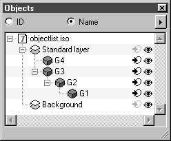
You can also use the following Object or group level option to ensure that only certain objects or groups are assigned a callout. As with Objects window described in this section, objects and groups can contain nested subgroups. The first level contains all objects and groups located on the same level as the first object or the first group underneath the standard layer.
In the example, these are the objects G4 and G3. The object G2 is located on the second level and the object G1 on the third.
Enter the required level in the entry field, in accordance with the entry made previously.
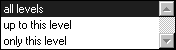
The pop-up menu allows you to select one of three settings.
When you select all levels, all objects and groups will receive a callout in accordance with the setting made under Create callouts. The up to this level setting records all objects and groups located on the level entered and the levels above this. If you only want callouts for objects and groups on one level on the drawing, select only this level. You can use this setting to create callouts successively on different levels.
If you select Only visible objects, a callout is only created for those objects or groups that are currently visible. Visible objects or groups are designated by the presence of the eye symbol in the Objects window. If objects or groups are invisible, you will see a closed eye symbol next to them.
Callouts
For Callout style, select one of the styles offered. All the same styles are displayed as those in the list in the Callouts window.
You can also create the callout entry from the associated ID or name by selecting Text created from for objects. This selection is only available if the required callout style does not use a scheme.
The entry under Gap between extent and callouts defines at what distance from the extent of the drawing each of the callouts (text entries) is located. The extent of the drawing is a theoretical rectangle into which the drawing fits snugly. If you are creating callouts successively for different levels, you should enter different distances here because the callouts may lie on top of each other if the same distance is entered.
Min. gap between callouts allows you to specify the uniform distance between the text entries for the callouts. This ensures that even entries of different lengths are far enough apart.
Sort callouts allows you to set the order in which the callouts are to be assigned for the objects. If you select no sorting, the callouts are assigned in accordance with the list in the Objects window. With the settings clockwise and anti-clockwise, the callout is numbered continuously in the selected direction. If the callouts are generated from a list, the sort setting cannot be selected.
If you have assigned a direction, you can still define the position of the first callout via the Start angle. The starting position for the angle is the 3 o’clock position.
Objects on Illustration
Objects with a callout are defined uniquely. Sometimes, you have even used the name from the object info for the callout entry. If you use a spare part drawing with callouts for an electronic spare parts catalog, the callout entry is usually used as a link to the spare parts list. If object information is no longer needed for this or any other reasons, you can use the On object with callout option to remove hotspots and delete object info.
For objects for which no callouts have been assigned, you can also select remove hotspot and Delete object info under On other objects.