Projection
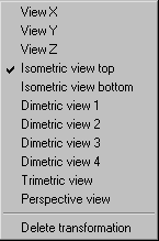
When the menu command Projection is selected, a pop-up menu appears with projection options. You can use these options in 3D mode to change the orientation of elements in space. Selecting a projection allows you to define the direction and distance from which you wish to view the elements.
| While working in 2D mode, the command is grayed out and cannot be selected. You can utilize projections in 3D mode when importing or pasting a 3D file. If you are working with the Rotational surfaces tool and Extrusion tool, you can use all the projections apart from Perspective view. |
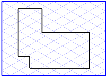
The different types of projection are described below. The figures show a simple object in the described orientation. To simplify matters, the hidden lines are depicted as in HLR display mode.
View X, View Y, View Z
If one of these views is selected in the pop-up menu, the elements will be displayed from the precise perspective of the axis in question. If the elements have not been rotated, this will give you the front view, side view and top view.
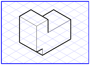
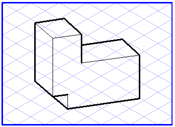
Isometric Projection Top, Isometric Projection Bottom
All elements are displayed in isometric projection. All the dimensions are shown with perspective reduction. The difference between the two variants lies in the fact that you are looking onto the elements from above in the first case and from below in the second.
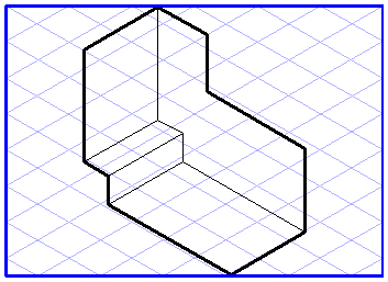
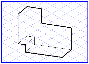
Dimetric Projections 1 to 4
The dimetric projections display the elements so that the major axes are imaged at angles of 7° and 42°. In the case of variants 1 and 2, you are looking onto the elements from above and in the case of variants 3 and 4 you are looking from below. The perspective reduction on the axis shown at an angle of 42° is 50%.
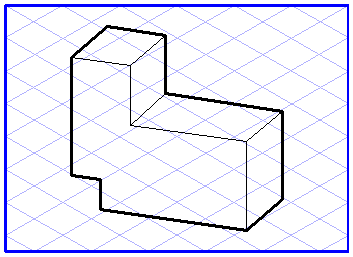
Trimetric Projection
Trimetric projection is the most general of all parallel projections. It shows the elements from the perspective of the Z-axis. Rotating the elements allows you to generate the orientation you want. All dimensions are subject to perspective reduction.
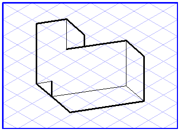
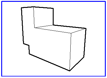
Perspective
Select the Perspective view projection to display all elements in a central perspective from the perspective of the Z-axis. Rotating around one of the axes creates a 2-point perspective, while rotating around two or more axes creates a 3-point perspective.
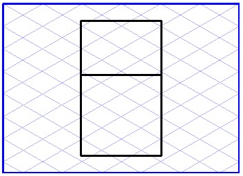
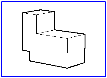
The distance from the observer to the object plays an important role with regard to perspective. Distance has a considerable influence on the perspective distortion of the elements. If it is small, the distortion is very large, if it is large, the distortion is small, i.e. parallel lines remain more or less parallel.
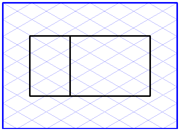
The figure on the left shows the object at a distance of 150 mm from the coordinate system origin, the one on the right shows the same object at a distance of 500 mm.
| Select a distance that is somewhat larger, since strong perspective distortions look unnatural. |
If you want to work with the
Perspective view projection, you should add the
3D Perspective Distance tool to the toolbar. This is the only way to influence distance. A description of how you can add items to the toolbar can be found in
Toolbars.
When Perspective view projection is selected, the 3D Perspective Distance tool in the toolbar becomes active. After selecting the tool, enter the distance in the dialog box.
Delete Transformation
This command in the pop-up menu allows you to undo various transformation operations. All elements are depicted in their original orientation again.