Display
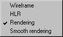
When the menu command Display is selected, a pop-up menu appears with display options. Each of these options depicts the drawing in a different mode when in 3D mode. As you can alter the display mode at any point, you should set the mode which is most suitable for the work you are currently doing.
You can also select the desired display mode using the standard toolbar (3D tools).
| While working in 2D mode, the command is grayed out and cannot be selected. If you are working with the Rotational surfaces tool and Extrusion tool and switch to 3D mode, you can use Wireframe and HLR display modes. |
Wireframe
The Wireframe option is used to display all the elements in the 3D file. This display mode is suitable if a drawing only contains a few objects.
HLR
If you select the HLR option, all the elements which are invisible to the observer because of the particular perspective and orientation will be removed. This function is very useful while working on a drawing in that it provides an overview of how the illustration will look later. The display is simpler than that of the subsequent 2D illustration in order to save time.
Rendering
If the loaded 3D data contains surfaces or solids, all the surfaces that have been created are depicted with color rendering when the Rendering option is selected. The light source is set by default.
If colors have been defined in the 3D data, these are adopted. If no colors have been created, a standard color is used for the contour. You can assign a new color to selected areas of the drawing via the Fills window.
Selecting this display mode gives you a good overview of individual parts, especially in the case of extensive assembly units. As it is just as fast to edit the drawing in this display mode as in Wireframe mode, you should opt for colored depiction of the drawing.
Smooth Rendering
Converting your drawing to Smooth rendering display mode also displays the drawing with color rendering. However, it has a smoother appearance than in Rendering mode. The grading of the rendering is smoothed and the transitions between pixels are softened. The difference is particularly noticeable on curved surfaces. This smoothing is achieved through interpolation. You can set the degree of smoothing by adjusting the smoothing angle value in the 3D Options preferences dialog box.
The Rendering display mode is normally sufficient for working in 3D mode. Smooth rendering is particularly recommended if the drawing is to be exported from 3D mode into a raster format. When exporting, the information of the drawing’s current display setting is used.
| Both Rendering and Smooth rendering display modes can only be used with imported and placed 3D files. When using the tools Rotational surfaces and > in 3D mode, neither of these display modes can be selected. |