Working in 3D Mode
You can use this window to determine the perspective and orientation of the drawing and can change the drawing using the tools provided.
Working in 3D Mode describes the tools. The options for editing using menu commands and the object window when importing structured data can also be used when placing data, provided you have object information (as is usually the case).
|
|
It is important to remember that the following limitations apply to the 3D mode functionality when working with placed files:
• The Arrow (+) tool cannot be used for individual surface elements in placed files.
• Layer options are unavailable. The drawing lies on the standard layer.
• Elements within objects cannot be identified during an update.
|
The drawing may be placed far outside the coordinate system if it has been created in its installation position in the CAD system. It is also possible that additional scattered elements from the CAD system have been saved in the 3D data and loaded into Arbortext IsoDraw CADprocess . In this case, click the Center elements tool.
If you have finished editing the drawing in 3D mode, click the
Convert to 2D illustration
button in the toolbar.
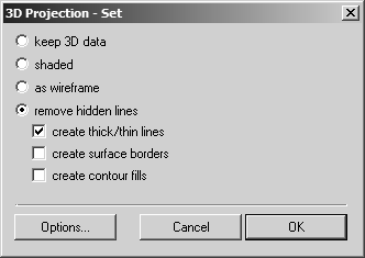
If the option has been selected in the preferences, as when importing 3D data, the 3D Projection-Set dialog box appears with the options for setting the style attributes for a technical illustration.
The setting options in this dialog box and in the
Options dialog box are the same as for imported files ( > command). All the settings are described in detail in the
Working in 3D Mode.
| Please note that, unlike during the import process, you cannot delete the lines generated by selecting option create surface borders in the 2D window. If there are too many additional elements visible on the placed file, switch back to 3D mode and disable the option while terminating the 3D transformation. |
Optimizing with Placed Illustrations
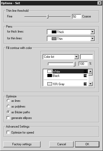
Click remove hidden lines in the 3D Projection-Set dialog box, then Options. The following dialog box appears as when importing:
The individual setting options are described in
Working in 3D Mode.
Thin Line Threshold
Since you are unable to edit individual elements in placed illustrations in the 2D window of Arbortext IsoDraw CADprocess , it is particularly important to find the optimum setting for the Thin line threshold function. The inner edges (thin lines) inserted during projection cannot be removed.
First, select Factory settings (50) for the threshold and take a close look at the result in the Arbortext IsoDraw CADprocess window. If the result is not accurate enough, change back to 3D mode and adjust the Thin line threshold setting. You can change to 3D mode and adjust settings as often as necessary.
Particularly when working with large amounts of data, you can see the results of your settings in the current drawing in 3D mode before initiating the conversion process. This allows you to see a preview of the converted drawing without needing to delay the conversion process. The drawing must be depicted in HLR display mode to do this.
To view the preview, select > , then the 3D Options dialog page. Change the Thin line threshold on this dialog page. To make the new setting visible on the drawing in 3D mode, close the 3D Options dialog page by clicking OK.
| Particularly when working with IGES files, you can specify the number of triangles that are to be created by adjusting tessellation accuracy. This in turn affects the result of the inner edges that are applied. If you want to change tessellation accuracy you must re-place the 3D data after making the relevant adjustments. |
Pens
If you subsequently want to change the attributes of the Pens, change to 3D mode. All the pens for the placed file will be available there.
Optimize
Under Optimize, set as Bézier paths. This gives the best result.
After completing 3D-mode editing by clicking OK in the 3D Projection-Set dialog box, the placed file appears as edited on the drawing sheet in the open file.
If you select the drawing, you will see that the marking consists of four red dots. You will not be able to select individual elements of the drawing and will therefore be unable to edit them with the Arbortext IsoDraw CADprocess tools. This is also not necessary, since you can use the technology of Arbortext IsoDraw CADprocess to generate a technical illustration for your spare parts catalog or operating instructions.
If the drawing has to be adjusted further, choose > . The placed drawing then appears – as when importing 3D data – in 3D mode.