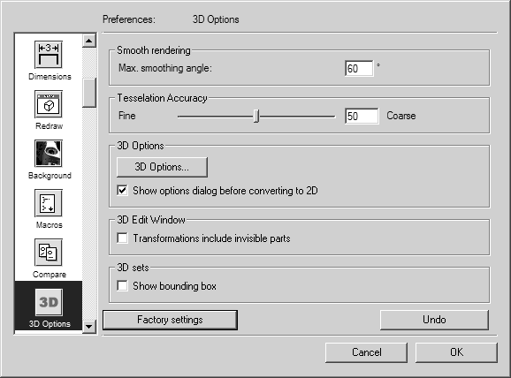
3D Options
The
3D Options
preferences panel contains settings that affect:
• The smoothness and accuracy of imported 3D contours and surfaces.
• 3D projection into a 2D illustration.
• The ability to transform invisible parts in 3D mode.
• The visibility of 3D set bounding boxes in 2D mode.
Smooth Rendering
This is where you can specify the smoothness for the Smooth rendering display option. The value entered for the smoothing angle affects the color grading between colored pixels. You can enter a value between 0 and 120. Using the default setting usually produces a good result in terms of depicting the color of your drawing. The higher the value, the softer the transitions between surface triangles are depicted. If a drawing contains several curved surfaces (cylindrical or spherical), a higher value for the angle produces a better result in the drawing. If the value is too high, this can lead to unwanted effects on straight surfaces. In certain circumstances, lines that are to be viewed as edges are also smoothed (e.g. a chamfer on a part). When deviating from the default settings, change the value little by little and monitor the effect on the drawing.
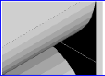
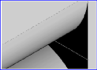
The examples illustrate the difference between Rendering and Smooth rendering. The figure on the left in rendering display mode depicts the curved surface with a stepped color blend. When smooth rendering is used, as in the figure on the right, the transitions between colors are barely visible.
Tessellation Accuracy
When importing IGES filesArbortext IsoDraw breaks up the surfaces it has loaded into triangles. This process is known as tessellation. The number of triangles created is determined by the setting. The setting allows you to specify how accurately the surfaces in the 2D illustration are to correspond to those of the 3D data. The rendering process as applied to the depiction of colors in 3D mode is also influenced by this setting. The value in the entry field has no unit. It ranges from 1 to 100 and tells you how coarse or fine the deviation of a surface will be after converting 3D data to a 2D illustration. The lower (finer) you set the value, the more accurately the surface will be adjusted. You can enter the value directly or use the slider.
The setting is particularly useful in the case of free-form contours and in the case of surface elements which touch at acute angles if no outer edges are involved. If the setting is very coarse and if two surfaces contact at too large an angle or if surfaces are curved, it is possible that no lines for the inner edges will be found. Since the generation of inner edges also always depends on the setting of the Thin line threshold function, the interplay between the two settings is important.
When the setting is finer, Arbortext IsoDraw CADprocess creates more triangles. This means that more inner edges can also be implemented. Since the setting is used for the entire drawing, a very fine setting coupled with a fine setting for the Thin line threshold can result in unwanted inner edges.
| The default setting 50 usually provides good results. If you wish to try a different setting, you must change the value before importing the 3D data. |
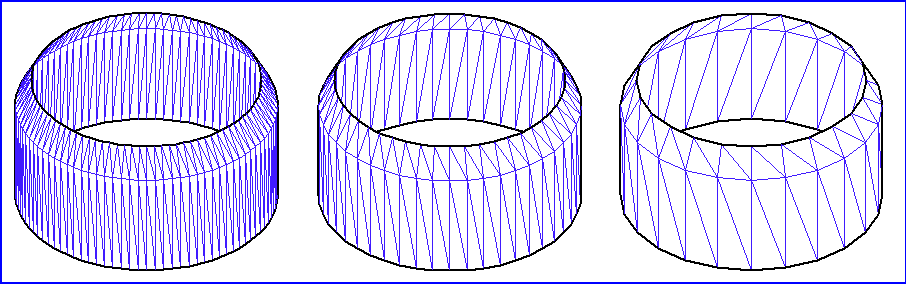
The following three examples illustrate the effect of tessellation settings. To make the effect clear, the Thin line threshold has been set to 0 in each case. This means that all possible inner edges are depicted following projection. The example on the left shows the result with a very fine setting (value 1). The triangles that are created are very small and the contour is very accurate. The default value of 50 has been used in the example in the center. The coarsest value 100 has been set in the example on the right. Few triangles have been created and the contour deviates more significantly from the 3D data settings.
| The finer the setting, the more accurately the contour is depicted. However, at the same time, the amount of data increases due to the large number of elements. This influences the calculation time during work in 3D mode and during projection. The files also take up greater storage space. The settings for tessellation accuracy (splitting surfaces into triangles) are only applied when importing or placing IGES files. If 3D data already consists of tessellated data – as in the case of e.g. VRML and Wavefront formats – these cannot be affected by the setting. |
3D Options
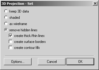
Clicking the 3D Options button opens the 3D Projection-Set dialog box with the settings for projecting the 3D data into a 2D illustration. You can preset the settings for all projections in the preferences. If the box next to Show options dialog before converting to 2D is not checked, the settings are applied during projection.
| Working in 3D Mode covers all the 3D options settings in detail with sample drawings. The following description is therefore restricted to only the most important information. |
The 3D Projection-Set dialog box appears as follows:
Keep 3D Data
If you select keep 3D data, the drawing is depicted in 2D mode using the display mode that was last selected in 3D mode. You cannot edit the drawing. You can make individual objects invisible using the object window. As this type of projection preserves all 3D information, you can change to 3D mode at any time using the 3D Transformation command in the Element menu. You can then edit the drawing in 3D mode.
| If animations have been created for objects in 3D mode prior to projection, only the following projection types can be selected in the 3D Projection-Set dialog box. |
Shaded
If you select shaded, the drawing appears in the Arbortext IsoDraw window as a raster image according to the display type selected in 3D mode. This type of projection is primarily intended for use with the Rendering and Smooth rendering display types in 3D mode. The drawing is converted as a raster image containing all the colors specified in 3D mode. After conversion, the drawing can be changed using the image editing tools.
As Wireframe
If you select as wireframe, all the elements in the 3D file will be transferred to the 2D illustration. The pens with their attributes from the 3D file are retained. The result of your 3D projection therefore corresponds to the original drawing from the CAD system.
Remove Hidden Lines
If you select remove hidden lines, the illustration will be displayed in your chosen perspective and orientation without hidden lines. This means that all elements are removed, which are invisible to the observer.
Create Thick/Thin Lines
If you click the create thick/thin lines box, the illustration will show the distribution of thick and thin lines for outer and inner edges, which is typical for technical illustration. The pens for thick and thin lines can be assigned in the Options dialog box.
Create Surface Borders
When importing 3D data, a large number of individual surface elements are loaded, particularly with the IGES format. If a file appears in 3D mode, you can easily recognize the surfaces with their delimiting lines as created in the CAD file.
If you select the create surface borders box, the missing inner edges are also converted from the delimiting lines. These lines are assigned a pen of their own in the 2D illustration.
Clicking Cancel allows you to exit the 3D Projection-Set dialog box. All changes are rejected. Clicking OK applies the current setting status to the projection. The settings are applied until the next change is made.
Options for Projection Type of Shaded
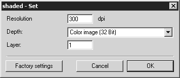
If you have selected shaded for the 3D Projection-Set, you can select various criteria in the shaded dialog box that can be used to save the raster image in Arbortext IsoDraw format.
Click Options in the 3D Projection-Set dialog box. The shaded dialog box appears as depicted below:
Resolution
Enter the required resolution here. The resolution defines how many pixels are present per inch (dpi = dots per inch). The higher the resolution, the better the quality. This however, also rapidly increases the size of the file at the same time.
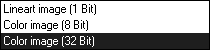
Image Depth
Select here whether the drawing is to be converted into black/white or one of the color modes. The image depth (bit depth) option essentially allows you to control how many different colors the Arbortext IsoDraw CADprocess file can contain. A line-art drawing can only contain black or white pixels. Color images are limited to 256 colors (8 bits) or any of the settings up to and including 16.7 million colors.
Layer
Specify here whether object information is to be taken over during conversion. The Layer that is to be entered here refers to the layers where objects within the file structure are located. Assemblies (objects) can contain subassemblies etc. Every icon in front of an object indicates a layer.
If 1 is entered next to Layer, all object information is discarded. All the objects are located on one layer. If you wish to preserve object information including all layers from the 3D-mode file, you must count the layers in the object window and enter the total next to Layer.
| Once the file has been converted with a sufficient number of layers, each object in the raster image can be individually selected and edited. |
Options for Projection Type of Remove Hidden Lines
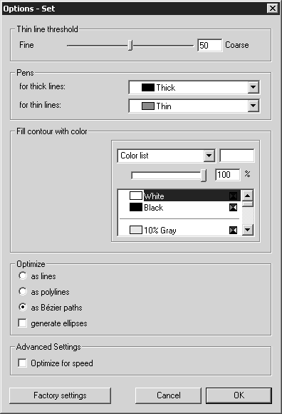
If you have selected remove hidden lines for the 3D Projection-Set, you can select the pens to be used for the lines in the Options dialog box next to the setting for the insertion of inner edges. Under Optimize you can specify the type of elements with which the illustration is to be saved in Arbortext IsoDraw format. Click Options in the 3D Projection-Set dialog box. The following dialog box appears:
Thin Line Threshold
This is where you can specify at which transitions between the triangular surfaces Arbortext IsoDraw CADprocess is to set thin lines, or inner edges.
| If you are importing or placing IGES files, the number of possible inner edges is also determined by the Tessellation Accuracy setting. |
The value in the display box has no unit and is used as a preference for internal calculations. You can enter values between 1 and 100. The higher (coarser) the value is set, the fewer inner edges are inserted. You can enter the value directly or use the slider.
You can see the results of your settings in the current drawing in 3D mode before initiating the conversion process. Particularly when working with large amounts of data, this has the advantage that you can see a preview of the converted drawing without needing to delay the conversion process. The drawing must be depicted in HLR display mode to do this. To make the new setting visible on the drawing, close the Options dialog box by clicking OK.
Pens
This allows you to select the Pens to be used for outer and inner edges. Select the pen for the outer edges in the for thick lines pop-up menu. Select the pen for the inner edges in the for thin lines pop-up menu.
Optimize
There are three ways of selecting how elements from 3D data are to be defined as elements in Arbortext IsoDraw CADprocess.
If you select as lines, the 2D illustration will only contain lines in the form of unconnected elements. If you select as polylines, several lines which follow on from each other are grouped together into polylines. Selecting as Bézier paths converts those elements of the 3D data, which follow on from each other into a Bézier path. Conversion to Bézier paths gives you the best results in terms of contour accuracy for the illustration. What is more, the number of elements is far lower than for line elements, what facilitates subsequent operation and also reduces storage requirements.
If you click the generate ellipses box, the elements that together make up an ellipse form are converted into an ellipse. The ellipses generated in this way optimize the 2D illustration and are easier to use subsequently.
Optimize for Speed
If you click the Optimize for speed button, simplified calculations are carried out in some cases during conversion. This accelerates the conversion process.
Factory Settings
If you click the Factory settings button in the Options dialog box, the settings in this window will be set to the selections recommended by the manufacturer. Experience has shown that these factory settings will deliver excellent Technical Illustrations for most 3D data.
Clicking Cancel exits the Options dialog box. All changes are rejected. Clicking OK applies the current setting status to the projection. The settings are applied until the next change is made.
Show Options Dialog Before Converting to 2D
Selecting this box calls up the 3D Projection-Set dialog box for the projection to a 2D illustration when you click the camera button in the toolbar. There you can change the settings for the current projection as specified in the 3D Options preferences dialog.
| You should select the dialog display if you wish to import unknown 3D data or need to convert very extensive data into 2D. This allows you to change the setting preferences prior to projection. |