Duplicating in 3D Mode
The Duplicate command works in exactly the same way in 3D mode as it does in the 2D mode of Arbortext IsoDraw.
The loaded drawing is duplicated. The duplicated drawing is positioned directly over the selected item.
3D Mode Example
Applies to Arbortext IsoDraw CADprocess only.
All selected objects, groups, and elements are duplicated. The following description shows how you can use the duplicate command in 3D mode.
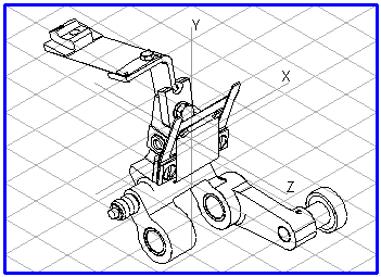
For an assembly unit consisting of numerous assemblies, you have selected a projection that enables most components to be identified with ease. However, you are unable to see either all or part of a number of important assembles when displaying these without hidden lines. To show these components, they would need to be viewed from a different direction.
The contour of the assembly (in this case, the front contour of the guide piece at the top of the lever) cannot be identified easily in the projection. However, the illustration needs to be able to show this contour in order to describe how the unit works.
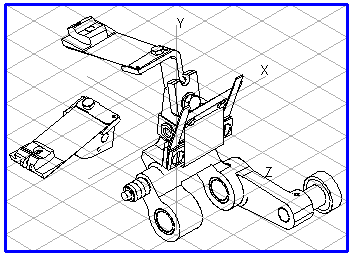
Select the assemblies (in this case, the lever with add-on parts) using the arrow cursor in the drawing or in the object window, then choose > . The duplicated assemblies remain selected.
They must now be moved into an empty part of the drawing. Choose > and select the direction of movement. Once the command has been completed, the components are located next to the original drawing. Click the Rotation tool in the toolbox. Select the axis in order to rotate the components in the required direction (in this case, the Y axis). Enter the rotation angle in the dialog box (in this case, 90). After you have confirmed your entry, the components will be displayed so that the contours (in this case, the contour of the guide piece) are clearly visible.
You can use the Duplicate function and the tools in 3D mode to generate as many additional views you require.