Introduction to 3D Mode
Whenever a file with 3D data in one of the supported formats is opened or placed, Arbortext IsoDraw CADprocess operates in 3D mode. There are two distinct features in 3D mode that enable you to distinguish it from the usual working window. The first is a three-dimensional coordinate system on the drawing area and the second is a standard toolbar with a range of tools.
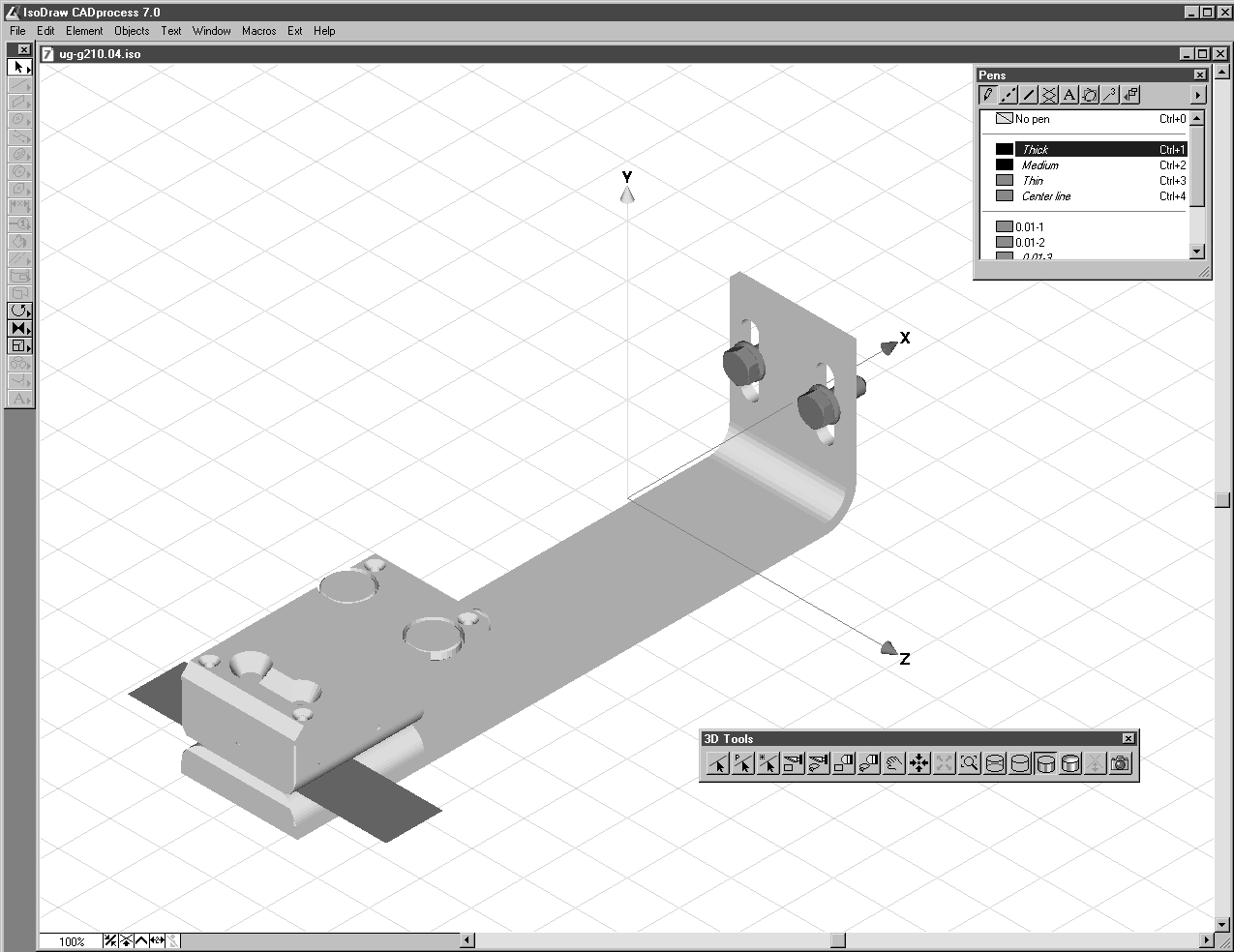
The figure below contains a window with these typical 3D-mode features.
The following description of working in 3D mode relates to structured 3D data for the IGES, VRML, and Wavefront formats. For AutoCAD DWG and DXF formats, the files consist of surfaces instead of objects or groups.
The drawing converted from 3D data still contains all 3D information. In order to process this information, this data must be converted into a 2-dimensional illustration. To allow you to utilize all the possibilities which 3D data offers, you can use various tools and menu commands to change data in 3D mode. Each edit function can be applied to both the entire drawing and/or selected assemblies. Once you have edited the drawing, the optimization process represents the last step from the CAD drawing to the technical illustration. Before they are converted to 2D illustrations, placed files can be edited in 3D mode in the same way as imported files.