Generation
To draw a rectangle, select the
Rectangle
tool from the toolbox. The cursor becomes a drawing

cursor.
Use the drawing cursor to click on the drawing area and, while still holding down the mouse button, drag the outline of the resulting rectangle across the screen. Release the mouse button when the rectangle meets your requirements.
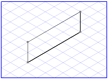
The start point is the point from which you started dragging the rectangle. The end point is the point at which you released the mouse button. The start point and end point lie diagonally opposite each other.
Unlike the
Rectangle tool, the tool for
Drawing of rounded rectangles
generates several individual elements: These elements include four lines and four ellipse segments which form a rectangle with rounded corners.
When dragging rounded rectangles, the tool behaves like the variant without rounding. The individual elements are generated upon releasing the mouse button. These individual elements can be edited in the same way as described for lines and ellipses.
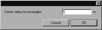
You can set the radius for the corners using the
Corner radius for rectangles
tool, last symbol in the pop-up menu for rectangles. The following dialog box will appear when this tool is selected:
Enter the required corner radius which will be used from this point onwards. Then click OK to confirm your entry or Cancel to close the dialog box without applying any changes you have made.
| Set the corner radius prior to generating a rounded rectangle. This is quicker than having to change the individual elements later. |
Grid Alignment
The orientation of the rectangle depends on whether or not the
Grid Alignment function has been activated when the rectangle is generated. If the
Grid Alignment function has been activated

, you can only generate perspective rectangles. The orientation of the sides is then governed by the grid which is currently set.
Without
Grid Alignment
, a rectangle with four 90° angles is produced.
This setting can be temporarily reversed by holding down the ALT key while dragging.
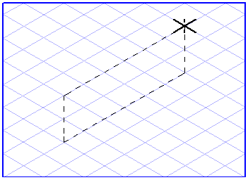
The orientation and, consequently, the shape of a perspective rectangle depend on the direction in which you drag the rectangle from the start point. The rectangle is forced onto one of the three major planes of the current grid depending on the direction in which it is dragged.
| Should you have any difficulties in determining the orientation of a perspective rectangle, try the following technique. Click the drawing area with the Rectangle tool and, holding down the mouse button, move the cursor in a circular pattern. You will now see how the orientation and the shape of the displayed rectangle change. |
Grid Snap and Element Snap
The start and end points of a rectangle can be attracted by neighboring grid and element points. Whether or not they are attracted depends on the current setting of
Grid Snap
and
Element Snap
.
The Grid Snap setting can be temporarily reversed by holding down the CTRL key while dragging.
Show Dimensions on the Element
If the
Show dimensions
option has been activated, length information relating to the pairs of parallel sides is displayed when the rectangle is dragged. In the case of perspective rectangles, the lengths are shown along the two major axes involved. The width and height are displayed for rectangles with four 90° angles.
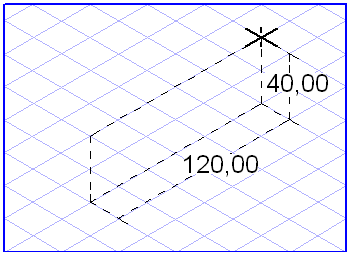
Displaying Dimensions in the Dimensions Bar
The dimensions bar shows a maximum of four dimensions when a rectangle is dragged. The first two fields show the width and height of the rectangle without perspective foreshortening. The third and fourth fields show the actual dimensions of the rectangle, i.e. the true lengths. If a rectangle has been selected, you can change every dimension directly in these fields. Confirm your entry with the ENTER key. If you do not confirm your entry, Arbortext IsoDraw will confirm it automatically after a few seconds. Use the TAB key to move from one field to another.